Device for changing load at any phase of movement

a technology of load change and load, which is applied in the field of sports training equipment manufacturing, can solve the problems of increasing the load of sportsman's muscles, increasing the weight of additional burden, and increasing the burden of additional burden, and achieves the effect of smooth variation of load

Inactive Publication Date: 2012-12-11
FARBSHTEYN VADIM YURYEVICH
View PDF9 Cites 4 Cited by
  • Summary
  • Abstract
  • Description
  • Claims
  • Application Information

AI Technical Summary

Benefits of technology

[0007]The inventive device is herein proposed for changing a load in various phases of movement. In preferred embodiments, the device comprises a basic burden capable of vertical movement; a hinge with a horizontal axis; a lever having an end coupled to the hinge and capable of rotating around the horizontal axis; and a revolving means (a roller or a pinion) for revolving about an axis fixedly mounted on the basic burden and extending essentially parallel to the horizontal axis, wherein the lever freely leans against the revolving means. In embodiments, the device may preferably comprise a supplemental burden secured in the region of the other end of lever. The lever may consist of two parallel rods fixedly attached to each other and pivotable around a common horizontal axis, or the rods can be independent and each pivotable around its own horizontal axis. The device provides convenient varying the load in the positive and negative phases of movement. It's usable in fitness, or in other areas, where it is necessary to smoothly vary the load.

Problems solved by technology

Thusly, the weight of the chains creates an additional burden thereby increasing the load for muscles of the sportsman.
In the process of lifting the basic burden, the chain links get off the floor, increasing the weight of additional burden.
It demands the presence of a considerable quantity of chains, creates difficulties in their storage and moving in an exercise room.

Method used


Image

  • Device for changing load at any phase of movement
  • Device for changing load at any phase of movement
  • Device for changing load at any phase of movement

Examples


Embodiment Construction

[0013]While the invention may be susceptible to embodiment in different forms, there are described in detail herein below, specific embodiments of the present invention, with the understanding that the present disclosure is to be considered an exemplification of the principles of the invention, and is not intended to limit the invention to that as illustrated and described herein.

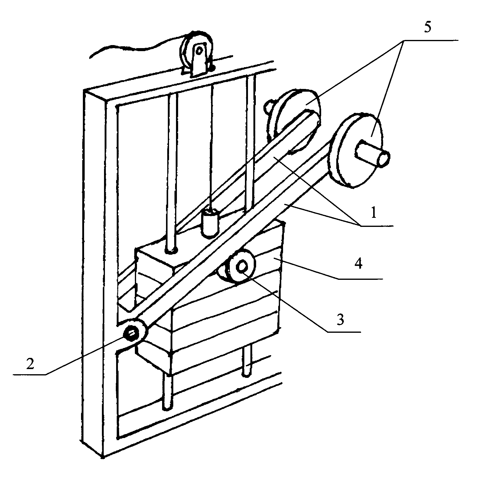
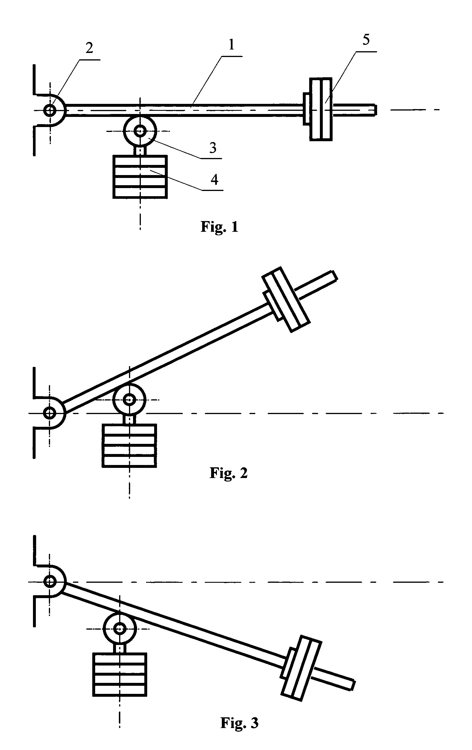
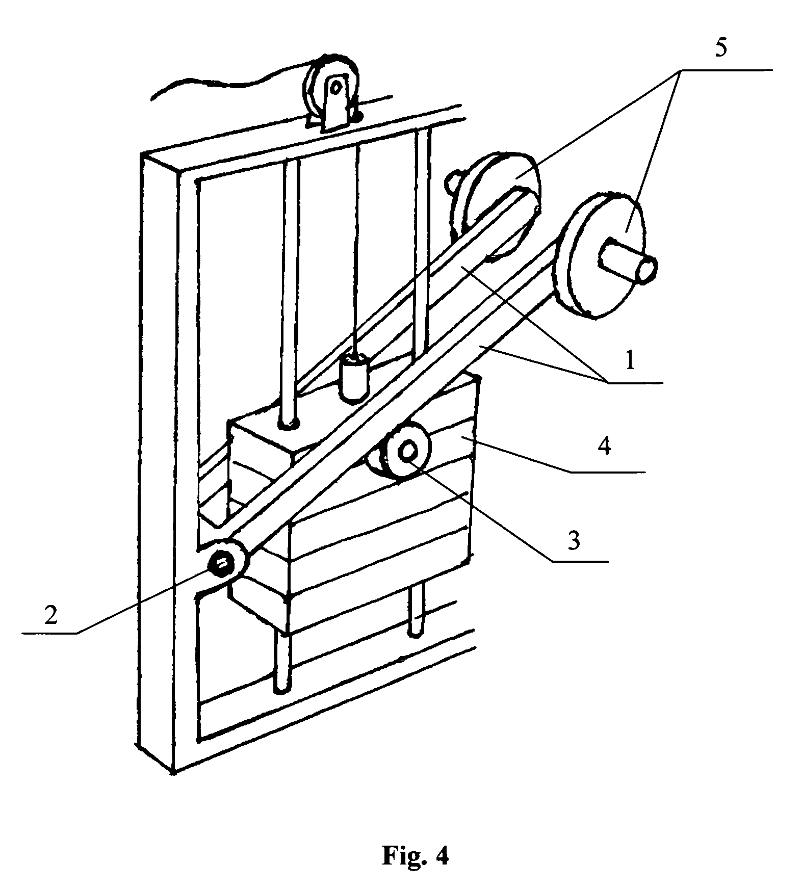
[0014]A preferred embodiment of the inventive device is illustrated on FIG. 1 and comprises a lever 1, having a first end fixed on a hinge with a horizontal axis of rotation 2; the lever 1 freely leans against a roller (or a pinion) 3, capable of revolving about an axis of rotation parallel to the axis 2. The axis of rotation of the roller (pinion) 3 is fixedly mounted on a basic burden 4 that can move only vertically.

[0015]Due to gravitation, the lever 1 acts upon the roller (pinion) 4 with a variable force depending on the shoulder determined by an angle of leaning against the roller (pinion) as illustrat...


PUM


Abstract

A device for varying a load applied to a vertical axis comprises a basic burden capable of vertical movement, a hinge with a horizontal axis, a lever having an end coupled to the hinge and capable of rotating around the horizontal axis, and a revolving means (a roller or pinion) for revolving about an axis mounted on the basic burden and extending essentially parallel to the horizontal axis, wherein the lever freely leans against the revolving means. In embodiments, the device may preferably comprise a supplemental burden secured in the region of the other end of lever. The lever may consist of two parallel rods fixedly attached to each other and pivotable around a common axis, or the rods can be independent, pivotable around the corresponding axis. The device provides convenient changing the load in the positive and negative phases of movement. It's usable in fitness, or for other purposes.

Description

CROSS-REFERENCE TO RELATED APPLICATIONS[0001]This application is a U.S. national stage application of a PCT application PCT / RU2008 / 000746 filed on 28 Nov. 2008, published as WO2009 / 082266, whose disclosure is incorporated herein in its entirety by reference, which PCT application claims priority of a Russian Federation application RU2007147696 filed on 20 Dec. 2007.FIELD OF THE INVENTION[0002]The invention concerns mainly the area of manufacturing of sports training apparatus, but also can be used in other areas of mechanical engineering, when it is necessary to smoothly increase or decrease the axial load applied to an axis.BACKGROUND OF THE INVENTION[0003]In trainings of sportsmen, mainly in bodybuilding and power-lifting, there is often a requirement of smooth increase in loading either in a positive, or in a negative movement phases.[0004]Adaptations for an increase of the load in the negative phase are unknown. For getting this effect in trainings, a sportsman usually uses the ...

Claims


Application Information

Patent Timeline
Patent Type & Authority Patents(United States)
IPC IPC(8): A63B21/062
CPCA63B21/0615A63B21/062A63B21/078A63B21/08A63B21/159A63B23/12A63B21/1492A63B21/00069Y10T74/1892A63B2021/0614A63B2021/0617A63B21/0628A63B21/0626A63B21/0617A63B21/4047A63B23/1209A63B23/03525
Inventor FARBSHTEYN, VADIM YURYEVICH
Owner FARBSHTEYN VADIM YURYEVICH
Why Eureka
Try Eureka