
Interprocessor direct cache writes

a direct cache and interprocessor technology, applied in computing, instruments, electric digital data processing, etc., can solve the problems of increasing complexity and access latency, increasing snooping and accessing caches coupled to other processors, and increasing complexity of accessing caches, so as to improve the overall system processing throughput and reduce inter-processor communication latency , the effect of improving the parallelism of processors

Active Publication Date: 2012-12-04
NVIDIA CORP
View PDF6 Cites 25 Cited by
  • Summary
  • Abstract
  • Description
  • Claims
  • Application Information

AI Technical Summary

Benefits of technology

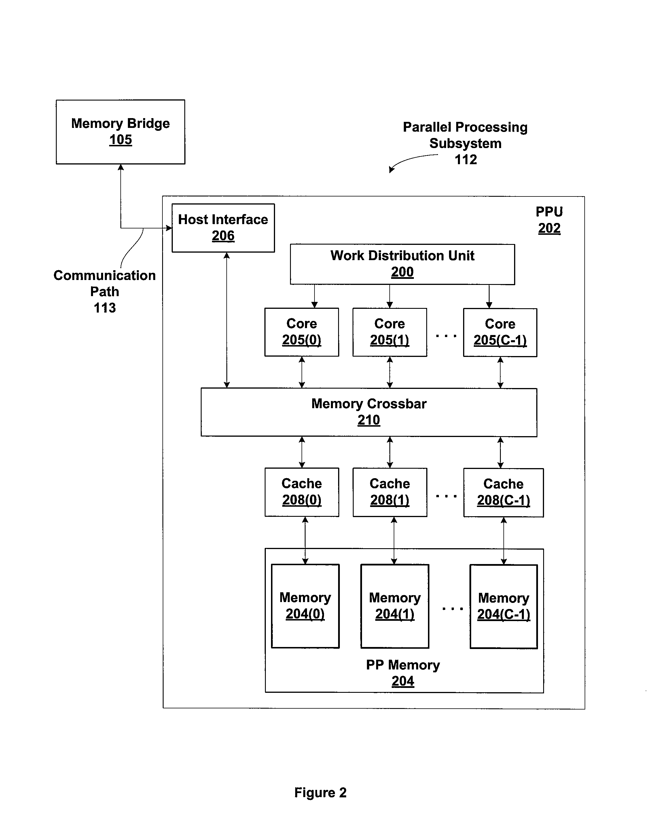
The patent describes a method and system for transmitting messages between processors in a multi-processor system. The system includes a central processing unit (CPU) and a parallel processing unit (PPU) with multiple processing cores and level 2 caches. The CPU produces messages and sends them to the PPU through a memory crossbar. The PPU stores the messages in its caches and updates a ready value to indicate that the message is available. The processing cores can then read the messages from the caches, reducing latency and improving processing throughput. The technical effects of this system include reduced inter-processor communication latency, increased processor parallelism, and improved overall system processing throughput without increasing complexity.

Problems solved by technology

As the number of processors in multiprocessor systems increases, the complexity of the snooping and accessing of caches that are coupled to other processors increases.
Therefore, the complexity and access latency increases as the parallelism increases.

Method used


Image

  • Interprocessor direct cache writes
  • Interprocessor direct cache writes
  • Interprocessor direct cache writes

Examples


Embodiment Construction

[0017]In the following description, numerous specific details are set forth to provide a more thorough understanding of the present invention. However, it will be apparent to one of skill in the art that the present invention may be practiced without one or more of these specific details. In other instances, well-known features have not been described in order to avoid obscuring the present invention.

System Overview

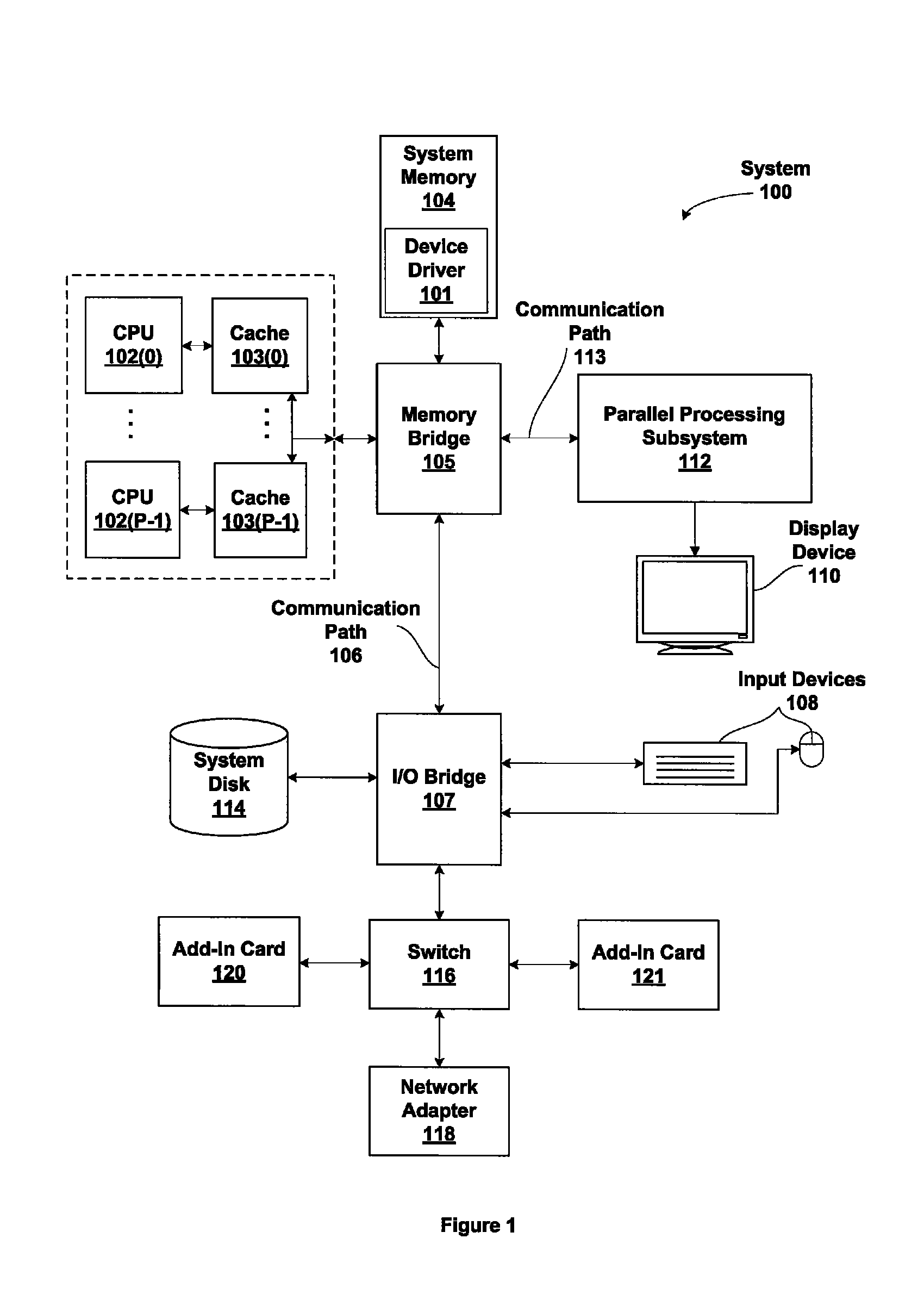
[0018]FIG. 1 is a block diagram illustrating a computer system configured to implement one or more aspects of the present invention. FIG. 1 is a block diagram of a computer system 100 according to an embodiment of the present invention. Computer system 100 includes one or more central processing units (CPU) 102, caches 103, and a system memory 104 communicating via a bus path that includes a memory bridge 105. In general, a computer system 100 includes a number P of CPUs and caches, where P≧1. (Herein, multiple instances of like objects are denoted with reference numbers ...


PUM


Abstract

In a multiprocessor system level 2 caches are positioned on the memory side of a routing crossbar rather than on the processor side of the routing crossbar. This configuration permits the processors to store messages directly into each other's caches rather than into system memory or their own coherent caches. Therefore, inter-processor communication latency is reduced.

Description

BACKGROUND OF THE INVENTION[0001]1. Field of the Invention[0002]The present invention generally relates to caching and more specifically to a multiprocessor system with caching on the memory side of a routing crossbar.[0003]2. Description of the Related Art[0004]Current multiprocessor systems include level 2 (L2) caches that are directly coupled to each processor. This configuration allows each processor to snoop writes to the caches of the other processors in the system and to access the caches with low latency compared with the number of clock cycles needed to retrieve data from system memory. System memory is typically accessed through a bridge device e.g., a Northbridge chip, and is shared with other devices in the system that are also coupled to the bridge device.[0005]As the number of processors in multiprocessor systems increases, the complexity of the snooping and accessing of caches that are coupled to other processors increases. Therefore, the complexity and access latency...

Claims


Application Information

Patent Timeline
Patent Type & Authority Patents(United States)
IPC IPC(8): G06F12/00
CPCG06F12/0815
Inventor DANSKIN, JOHN M.KILGARIFF, EMMETT M.GLASCO, DAVID B.TREICHLER, SEAN J.
Owner NVIDIA CORP
Learn More