
Sub-pixel structure and pixel structure of color electrophoretic display

a color electrophoretic display and subpixel technology, applied in the field of electrophoretic display, can solve the problems of reducing the light utility efficiency of the electrophoretic display, reducing the brightness, contrast and color saturation of the electrophoretic display, and achieving the effect of improving the light utility efficiency of the sub-pixel structure of the present invention

Active Publication Date: 2012-11-27
E INK HLDG INC
View PDF10 Cites 17 Cited by
  • Summary
  • Abstract
  • Description
  • Claims
  • Application Information

AI Technical Summary

Benefits of technology

The present invention relates to a sub-pixel structure of color electrophoretic display that improves the light utility efficiency of the display. The invention provides a pixel structure with a common electrode and a plurality of charged particles, wherein the charged particles have different colors and electrical properties. The charged particles can be arranged in rows, and the size of the charged particles can be different. The invention also provides a second sub-pixel structure with a different range of charged particles for achieving improved light utility efficiency. The invention improves the display's light efficiency and provides better light utilization, resulting in improved display performance.

Problems solved by technology

However, the light utility efficiency of the electrophoretic display is reduced by the color filter, and thus the brightness, the contrast and the color saturation of the electrophoretic display are reduced.

Method used


Image

  • Sub-pixel structure and pixel structure of color electrophoretic display
  • Sub-pixel structure and pixel structure of color electrophoretic display
  • Sub-pixel structure and pixel structure of color electrophoretic display

Examples


first embodiment

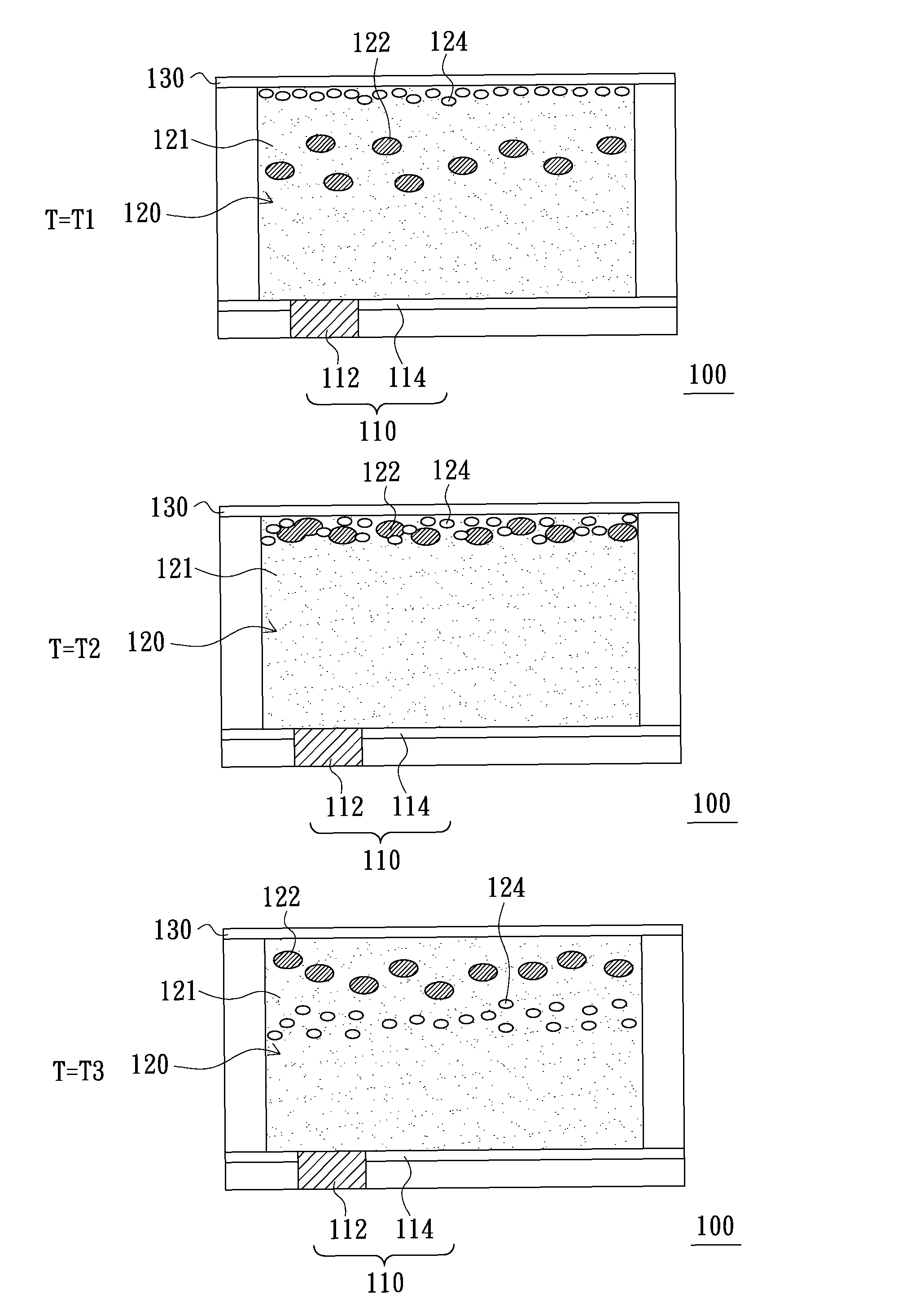
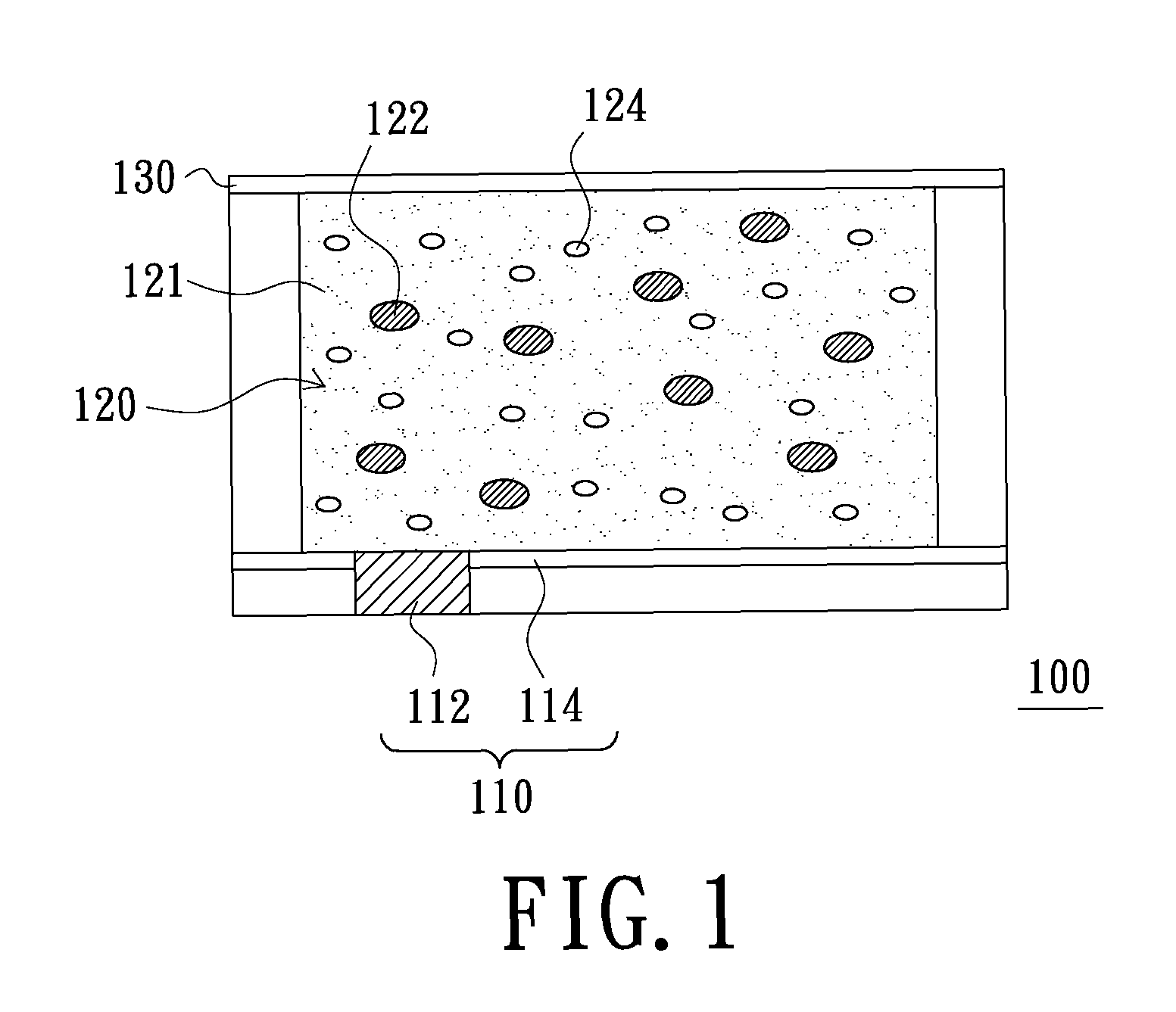
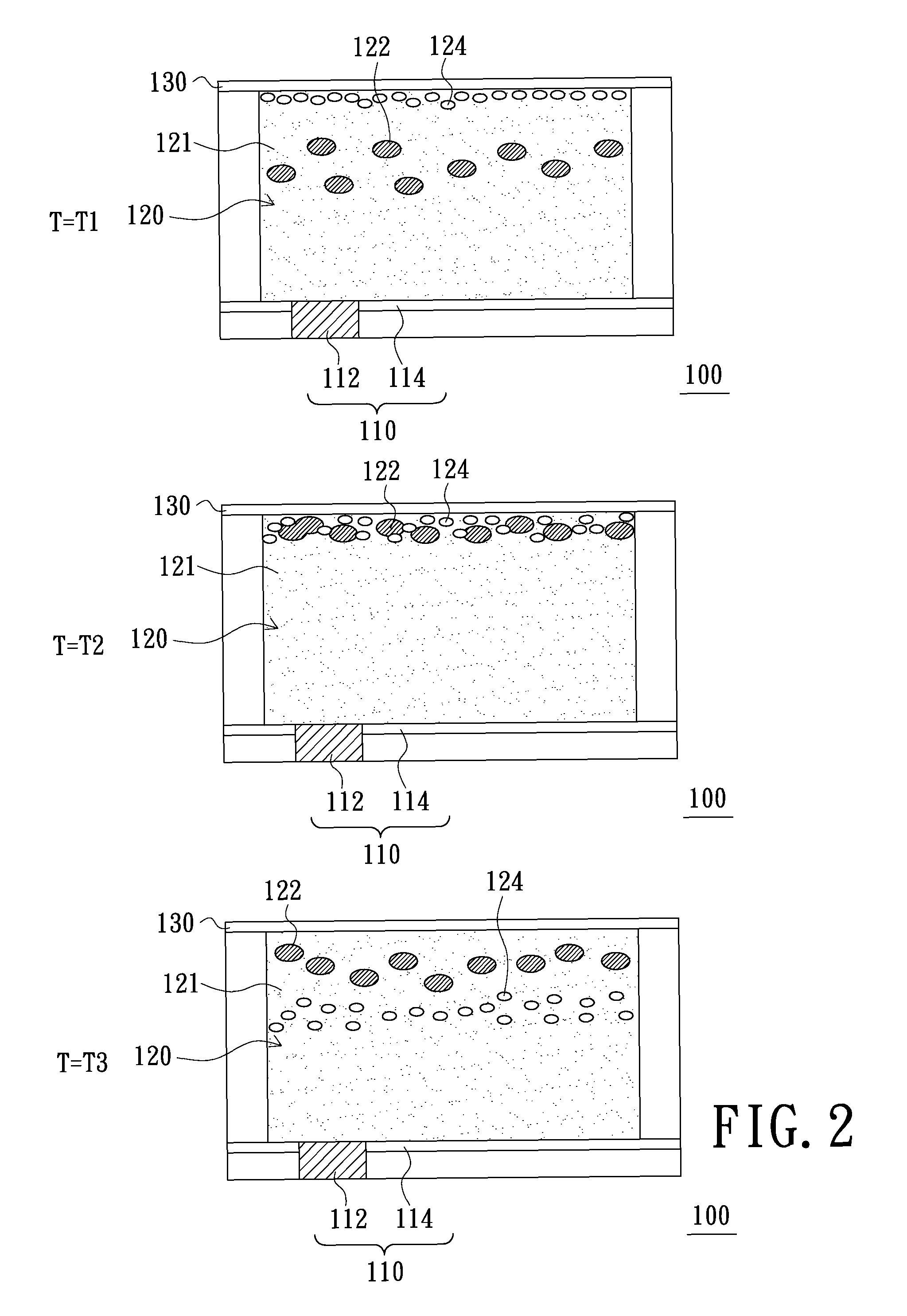
[0032]FIG. 1 is a schematic view of a sub-pixel structure of color electrophoretic display according to the present invention. Referring to FIG. 1, the sub-pixel structure 100 of a color electrophoretic display of the present embodiment includes a driving unit 110, a display unit 120 and a transparent electrode 130, wherein the display unit 120 is disposed on the driving unit 110, and the transparent electrode 130 is disposed on the display unit 120. The driving unit 110 can be an active driving unit or a passive driving unit, and the present embodiment takes the active driving unit as an example. The driving unit 110 includes a driving element 112 and an electrode 114 electrically connected with the driving element 112. The driving element 112 is, for example, a thin film transistor (TFT), and the electrode 114 can be served as a light absorbing layer. Moreover, the material of the transparent electrode 130 can be indium tin oxide (ITO), indium zinc oxide, (IZO), zinc oxide or indi...

second embodiment

[0048]The method to let the first sub-pixel structures 310a, 310b and 310c display different colors is similar to that of the second embodiment and is not repeated herein. Moreover, in another embodiment, the color of the first charged particles 122 of the first sub-pixel structure 310a can be cyan, the color of the first charged particles 122 of the first sub-pixel structure 310b can be magenta, and the color of the first charged particles 122 of the first sub-pixel structure 310c can be yellow.

[0049]FIG. 7 is a schematic view of a pixel structure of color electrophoretic display according to a fifth embodiment of the present invention. Referring to FIGS. 3 and 7, the pixel structure 400 of the present embodiment includes a plurality of first sub-pixel structures 410 and a second sub-pixel structure 420. Each of the first sub-pixel structures 410 includes a first driving unit, a first display unit and a first transparent electrode. The first transparent electrode is used as a commo...


PUM

PropertyMeasurementUnit
diametersaaaaaaaaaa
diametersaaaaaaaaaa
diametersaaaaaaaaaa

Abstract

A sub-pixel structure of color electrophoretic display includes a driving unit, a display unit and a transparent electrode, wherein the display unit is disposed on the driving unit and the transparent electrode is disposed on the display unit. The display unit includes a plurality of first charged particles and a plurality of second charged particles. A color of the first charged particles is different from a color of the second charged particles. Diameters of the first charged particles are greater than diameters of the second charged particles. The first charged particles and the second charged particles have the same electrical property. The sub-pixel structure of color electrophoretic display has high light utility efficiency.

Description

BACKGROUND[0001]1. Field of the Invention[0002]The present invention relates to an electrophoretic display (EPD), and particularly to a pixel structure and a sub-pixel structure of a color electrophoretic display.[0003]2. Description of the Related Art[0004]With the advancement of the flat display technology and the flat displays having advantages of light in weight, small in size and low power consuming, the flat displays have become more and more popular. In general, the flat displays includes liquid crystal display (LCD), plasma display panel (PDP), organic light emitting diode display (OLED display) and electrophoretic display, etc., wherein the electrophoretic display does not include light emitting source, so the electrophoretic display further has the advantage of power saving in comparison with other flat displays.[0005]The conventional electrophoretic display is a monochrome display. However, for promoting the market competitiveness of the conventional electrophoretic displ...

Claims


Application Information

Patent Timeline
Patent Type & Authority Patents(United States)
IPC IPC(8): G09G3/34G02F1/167
CPCG02F1/167G02F2203/34G02F2001/1678
Inventor WANG, YI-CHINGWANG, TZU-MING
Owner E INK HLDG INC
Learn More