
Aircraft having a reduced environmental impact

a technology of environmental impact and aircraft, applied in the direction of propellers, air-flow influencers, transportation and packaging, etc., can solve the problems of increasing noise pollution, increasing noise pollution, and thus reaching noise pollution, so as to reduce the power (and therefore noise and fuel consumption) of the turbine engine, and the effect of easy integration of the engine on the aircra

Inactive Publication Date: 2012-11-20
AIRBUS OPERATIONS (SAS)
View PDF41 Cites 15 Cited by
  • Summary
  • Abstract
  • Description
  • Claims
  • Application Information

AI Technical Summary

Benefits of technology

[0016]Indeed, and astonishingly, the applicant company has found that if, in an aircraft layout of the type recalled hereinabove and described in GB-1 397 068, the turbine engine is replaced by a propeller(s) propulsion system, then provided that said screening surface is positioned just below the propeller or propellers (whereas in GB-1 397 068 this screening surface is very much to the rear of the turbine engine outlet), then excellent attenuation of the noise of said propulsion system can be had, this attenuation being such that the noise emitted by this propulsion system, although intrinsically more intense that of a turbine engine, was far better screened by said rear part of the cell, and therefore far less intense in the surroundings of said aircraft.
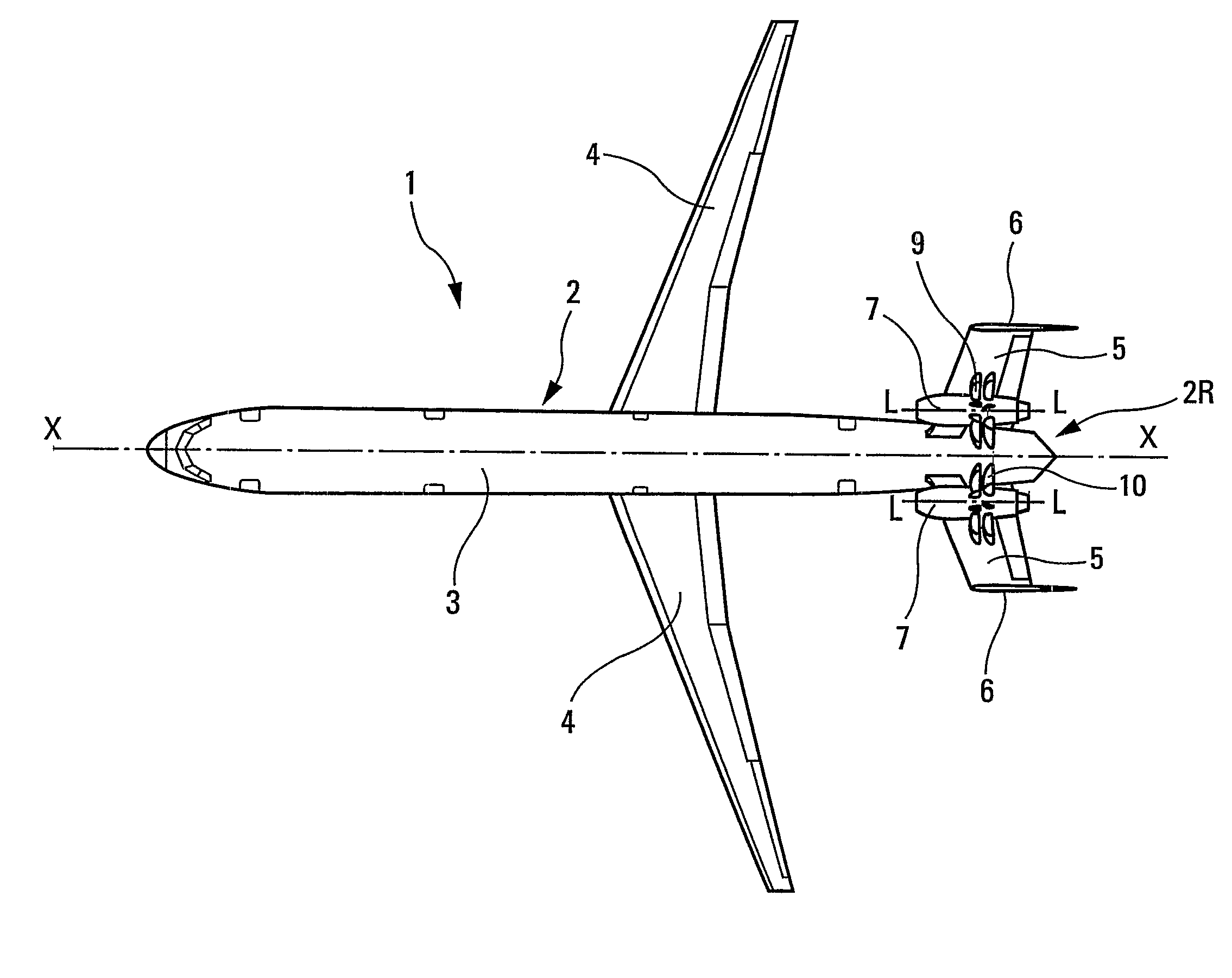
[0018]As a preference said propeller(s) is / are positioned behind said engine and is / are able to exert thrust on said aircraft. Thus, the propeller or propellers is or are located at a small cross-section point on the fuselage of the aircraft, leaving more space for installing it (them). In addition the propeller(s) is (are) thus distant from the passenger cabin, and this is then beneficial to passenger comfort.
[0019]Furthermore, in order as far as possible to limit the fuel consumption of the engine, it is preferable for said propeller or propellers not to have any peripheral cowling.
[0020]In addition, it is advantageous for said engine to comprise two coaxial contra-rotating propellers. This is because in this case, the diameter of said propellers is smaller, making it easier to integrate said engine onto the aircraft.
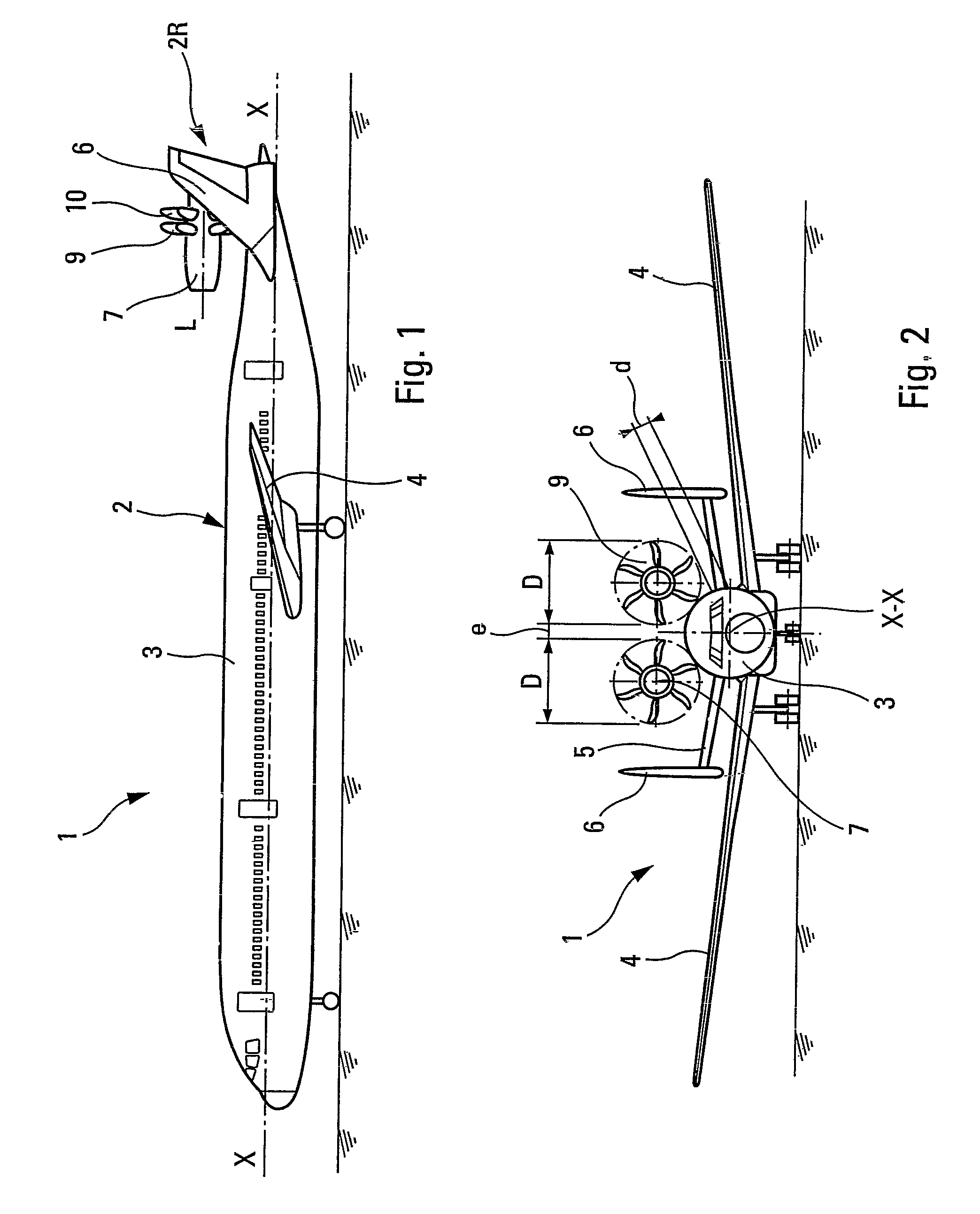
[0021]In order to avoid any aerodynamic interaction and any vibrational, particularly acoustic, interaction, between the propeller(s) and the rear part of the cell, it is advantageous for the shortest distance between the end of a propeller and said rear part to be at least equal to 10% of the diameter of said propeller.
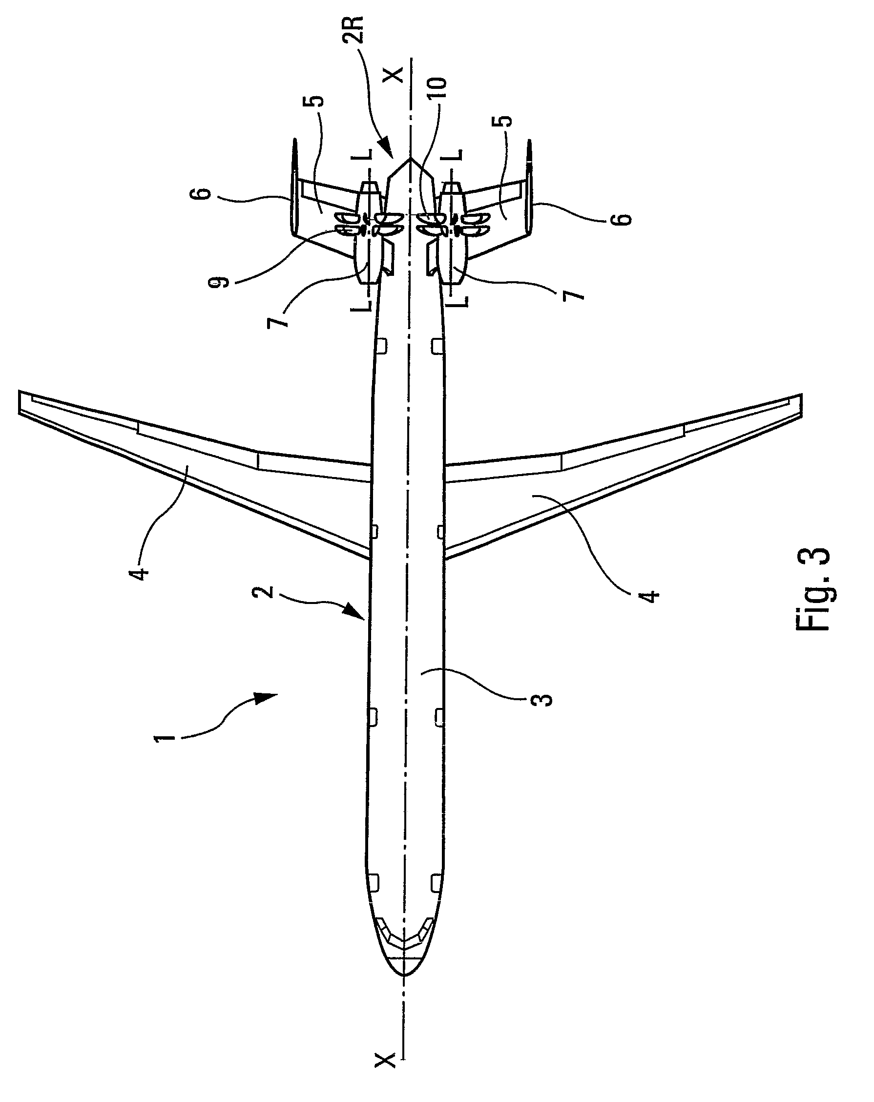
[0022]Of course, the aircraft according to the present invention may be a single-engine aircraft and have just one propeller(s) engine mounted at the rear in the way described hereinabove. However, in addition to the latter engine, it may also comprise at least two turbine engines borne symmetrically by the wings of said aircraft. An arrangement such as this is advantageous in that the rear propeller(s) engine, which is not very fuel-greedy and is not very noisy because of the noise screen according to the invention, means that the power (and therefore the noise and fuel consumption) of the turbine engines, can be reduced.

Problems solved by technology

However, most of existing aircraft are propelled by turbine engines which are therefore, on the one hand, greedy for fuel and, on the other hand, sources of environmental pollution through what they emit into the atmosphere.
However, in operation, propeller-type propulsion systems are even more noisy than turbine engines, which means that the advantage in terms of energy saving and reduction in environmental pollution from their emissions which are enjoyed when turbine engines are replaced by propeller-type propulsion systems, would be accompanied by the disadvantage of an increase in noise pollution.
The noise pollution thus reached would be unacceptable and, in any event, difficult to reconcile with the legislation currently in force.
The overall efficiency of the screen formed by the rear part of the cell is therefore not optimized.

Method used


Image

  • Aircraft having a reduced environmental impact
  • Aircraft having a reduced environmental impact
  • Aircraft having a reduced environmental impact

Examples


Embodiment Construction

[0030]The commercial airplane 1, according to the invention and depicted schematically in FIGS. 1 to 3, has a longitudinal axis X-X and comprises a cell 2 which consists of a fuselage 3, of wings 4, of a horizontal empennage 5 and of two vertical empennages 6. The wings 4 do not bear any engine and the vertical empennages 6 are positioned at the ends of the horizontal empennage 5.

[0031]Mounted at the rear of the airplane 1 are two propeller engines 7, positioned on the back of said airplane with their axes L-L parallel to the longitudinal axis X-X. The engines 7 are borne by pylons 8 (see also FIGS. 4 and 5) and are positioned side by side. At the rear end, each engine 7 has two un-cowled thrust-generating contra-rotating propellers 9, 10 of diameter D. The two propellers 9, on the one hand, and the two propellers 10, on the other, are positioned facing one another with a space e of at least 60 cm between them. Furthermore, the shortest distance d between the end of the propellers 9...


PUM


Abstract

An aircraft having a propeller engine mounted at the rear of the aircraft, on the back thereof, such that the axis of the engine is parallel to the longitudinal axis of the aircraft. The aircraft has a cell, the rear part of which comprises a horizontal empennage and two vertical empennages, positioned one at each end of said horizontal empennage. The propeller is positioned vertically in line with the rear part of the cell, and the rear part of the cell forms a lateral and downward barrier, on each side of a plane of the propeller, that screens an acoustic intensity equal to approximately−5 dB with respect to a maximum acoustic intensity emitted by the engine.

Description

FIELD OF THE INVENTION[0001]The present invention relates to an aircraft with reduced environmental impact.BACKGROUND OF THE RELATED ART[0002]It is known that propeller-type propulsion systems, for example turboprops with a single propeller or prop fans with contra-rotating propellers, display better energy efficiency than turbine engines.[0003]However, most of existing aircraft are propelled by turbine engines which are therefore, on the one hand, greedy for fuel and, on the other hand, sources of environmental pollution through what they emit into the atmosphere.[0004]Hence, as far as saving energy and reducing environmental pollution are concerned, it would be more advantageous for aircraft to be equipped with propeller-type propulsion systems rather than turbine engines.[0005]However, in operation, propeller-type propulsion systems are even more noisy than turbine engines, which means that the advantage in terms of energy saving and reduction in environmental pollution from thei...

Claims


Application Information

Patent Timeline
Patent Type & Authority Patents(United States)
IPC IPC(8): B64D27/00B64C11/48
CPCB64D27/02B64D27/14B64D2027/005Y02T50/66Y02T50/60
Inventor GALL, PIERRE-EMMANUELCROS, CHRISTOPHE
Owner AIRBUS OPERATIONS (SAS)
Learn More