
Apparatus for moving concrete pump hoses

a technology for moving concrete and pump hoses, which is applied in the direction of transportation and packaging, roads, and maintenance of roads, can solve the problems of difficulty in arranging pipes and hoses filled with concrete mixture, insufficient reach of the boom of the concrete pumping truck, and inability to use conventional boom trucks between buildings. it is easy to manufacture, and the effect of increasing the manpower and manpower of the apparatus for supporting and moving the concrete pump hoses

Active Publication Date: 2012-11-20
SOMERO ENTERPRISES INC
View PDF46 Cites 36 Cited by
  • Summary
  • Abstract
  • Description
  • Claims
  • Application Information

AI Technical Summary

Benefits of technology

[0009]It is another object of this invention to provide a greater range of movement for an apparatus operable to move concrete pump hoses.
[0027]It is a further object of this invention to provide a mobile apparatus for supporting and transporting a concrete pump hose, which is durable in construction, inexpensive of manufacture, carefree of maintenance, and simple and effective in use.

Problems solved by technology

It is difficult to use conventional boom trucks between floors of buildings because there may not be enough clearance between the floor and the overhead structures to reach the entire floor with the articulated boom.
Furthermore, the boom of the concrete pumping truck may also not be sufficiently long to reach most remote portions of the floor on which the concrete is being deposited, which would require the use of additional pipes or hoses to carry and place the concrete at those remote locations.
Although such systems are capable of reaching the remote areas from the concrete pumps, the pipes and hoses filled with concrete mixture are difficult to manipulate in order to properly place the concrete at the remote portions due to the substantial weight of the filled pipes and / or hoses.

Method used


Image

  • Apparatus for moving concrete pump hoses
  • Apparatus for moving concrete pump hoses
  • Apparatus for moving concrete pump hoses

Examples


Embodiment Construction

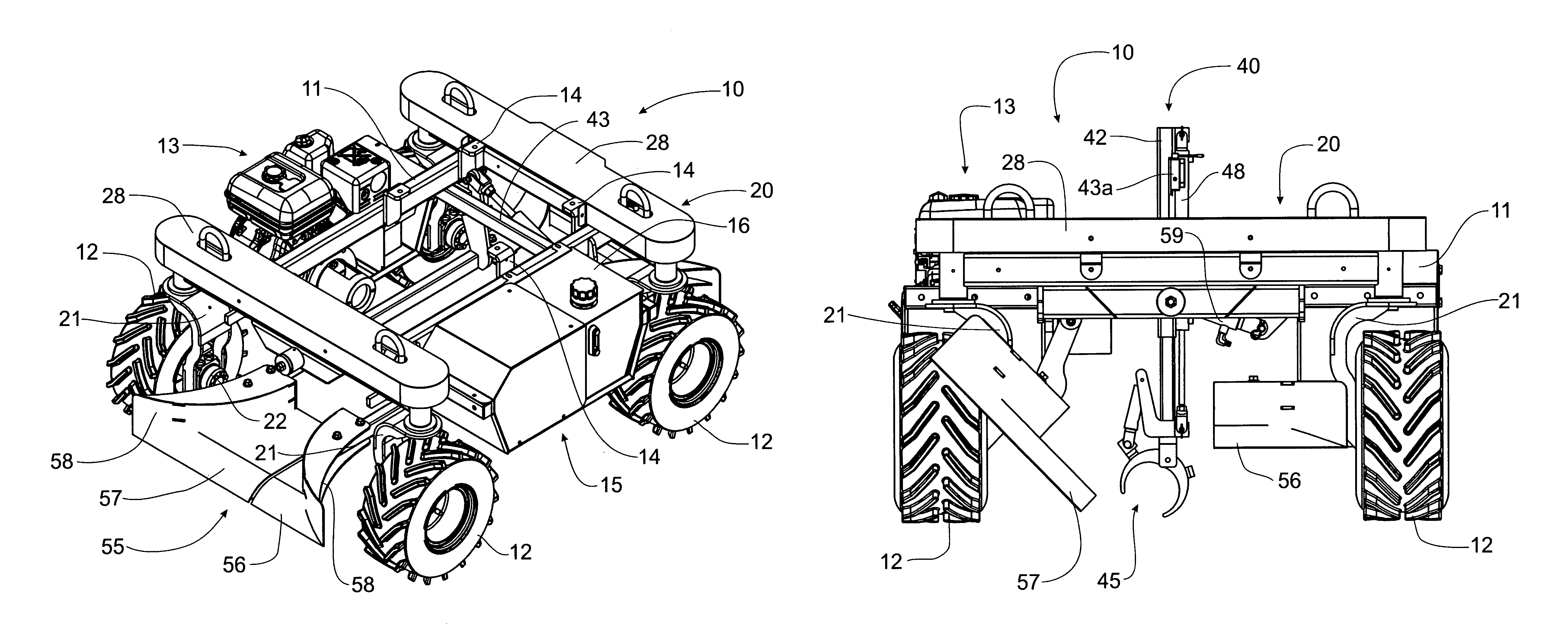
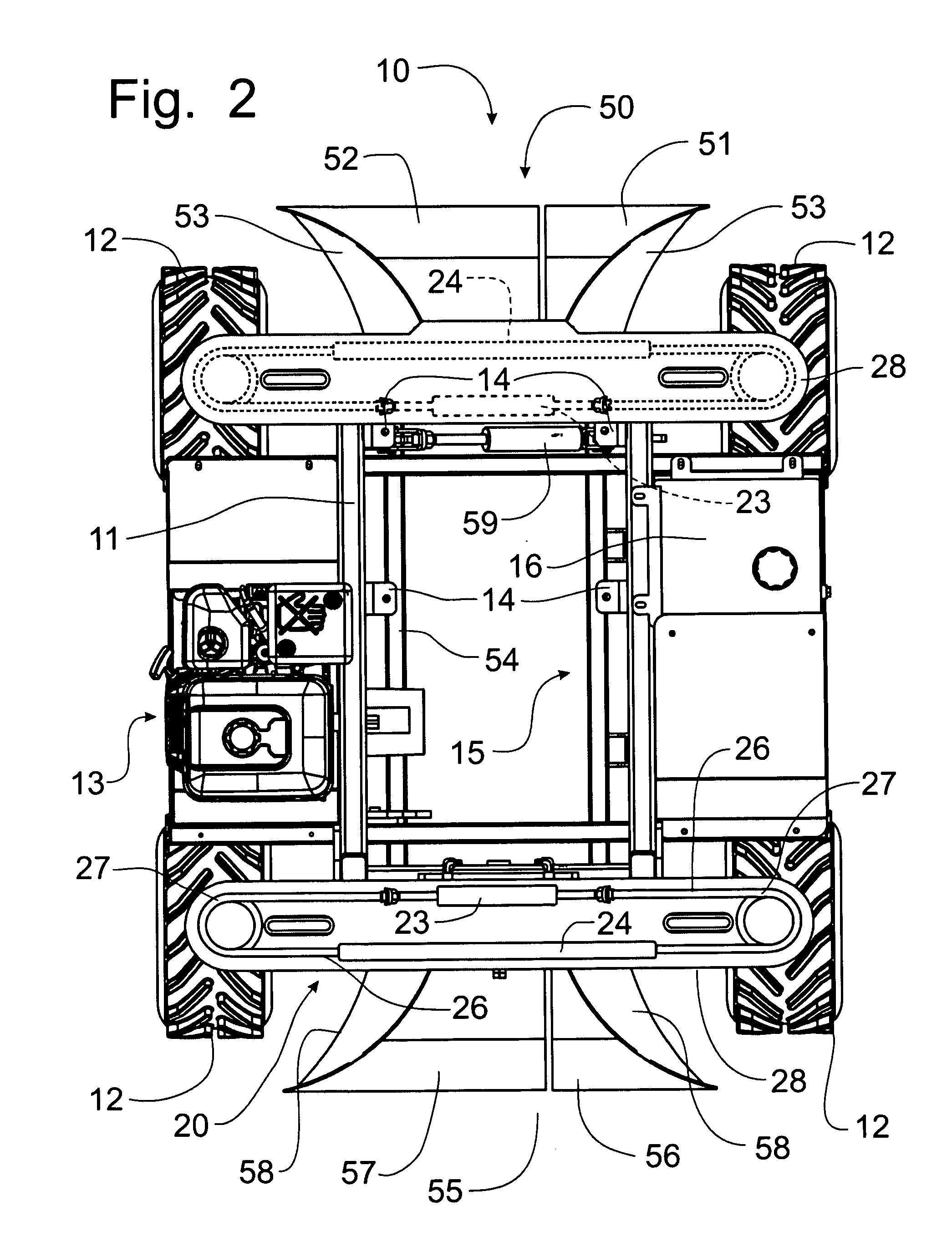
[0055]Referring to FIGS. 1-6, a mobile apparatus for supporting and moving a concrete pump hose or rigid pipe incorporating the principles of the instant invention can best be seen. Any references to right, left, front and rear are made as a matter of convenience and are determined by standing at the rear of the apparatus with the engine mounted on the left side of the apparatus. The mobile apparatus 10 includes a frame 11 supported on four independently powered wheels 12. The frame 11 supports an engine 13, preferably a gasoline engine, to serve as a power plant for the operation of the apparatus 10. The frame 11 also includes an attachment mount 14, described in greater detail below for the mounting of an operable attachment device.

[0056]Each wheel 12 is supported from the frame 11 by a support bracket 21 that rotatably supports the corresponding wheel 12 about a horizontal axis of rotation. When the wheels 12 are placed into a longitudinal orientation, as depicted in FIG. 1, a hy...


PUM


Abstract

A mobile apparatus moves a concrete pump hose over a base surface and has a wheeled frame in which the wheels are pivotable about a generally vertical pivot axis between a longitudinal orientation and a transverse orientation. Each of the front pair of wheels and the rear pair of wheels are coupled to a steering mechanism to permit independent pivotal movement of the respective pairs of wheels to provide four wheel steer of the frame. The hose is supported by front and rear horn members above the base surface and below the frame. An intermediate grappling apparatus engages the hose to affect elevation thereof onto the horn members. The horn members are split between a fixed portion and a pivotally movable portion that pivots away from the fixed portion to permit the hose to be elevated above the horn members. A boom apparatus can substitute for the grappling apparatus.

Description

CROSS-REFERENCE TO RELATED APPLICATIONS[0001]This application claims domestic priority on U.S. Provisional Patent Application Ser. No. 61 / 078,904, filed on Jul. 8, 2008, the contents of which are incorporated herein by reference.FIELD OF THE INVENTION[0002]This invention relates generally to devices for the placement of concrete to form a building floor and, more particularly, to an apparatus for moving the hose for conveying concrete pumped from a concrete pump truck into a low profile area where overhead obstructions preclude or limit the accessibility of the concrete pump truck.BACKGROUND OF THE INVENTION[0003]It is known to use a concrete pumping truck and pipe or a boom truck to place concrete at a targeted site. The boom truck incorporates boom and pipe apparatus to pump flowable concrete mixture to a remote location, which can be at a greater distance from the pumping truck or at a different elevation, such as an upper floor or a basement of a building. It is difficult to use...

Claims


Application Information

Patent Timeline
IPC IPC(8): B62D7/15E01C19/12
CPCB62D7/1509E01C19/182E04G21/0418
Inventor STOLTZFUS, DANIEL R.
Owner SOMERO ENTERPRISES INC
Learn More