
Smart keyless entry system

a keyless entry and keyless technology, applied in the field of smart keyless entry systems, can solve the problems of difficult to dispose of the transmitting antenna of the onboard device, door is locked, and door unlock is not conducted

Inactive Publication Date: 2012-11-13
MAZDA MOTOR CORP
View PDF10 Cites 10 Cited by
  • Summary
  • Abstract
  • Description
  • Claims
  • Application Information

AI Technical Summary

Benefits of technology

This configuration ensures accurate recognition of the portable device's location, preventing incorrect locking or unlocking scenarios by adjusting signal strength based on the operated door, thus maintaining proper vehicle compartment access control.

Problems solved by technology

Accordingly, it may be difficult to dispose the transmitting antenna of the onboard device of the smart keyless entry system at the central portion of the front portion of the vehicle compartment in the vehicle width direction.
Therefore, if the output strength of the transmitting antenna is set in such a manner that its output range reaches one of the doors which is closer to the transmitting antenna than the other door, without reaching the other door, for example, the area of the other door is out of the output range of the request signal, so that there is a concern that it may be recognized (determined) by mistake that the portable device is located outside the vehicle compartment despite the inside existence of the portable device in the vehicle compartment.
This may cause a problem in that the door is locked, leaving the portable device inside the vehicle compartment.
As a result, the portable device may be mistakenly recognized to be located inside the vehicle compartment despite its location outside the vehicle compartment.
In this case, there may occur a situation in which the door unlock is not conducted even if the access switch at the door is operated.

Method used


Image

  • Smart keyless entry system
  • Smart keyless entry system
  • Smart keyless entry system

Examples


embodiment 1

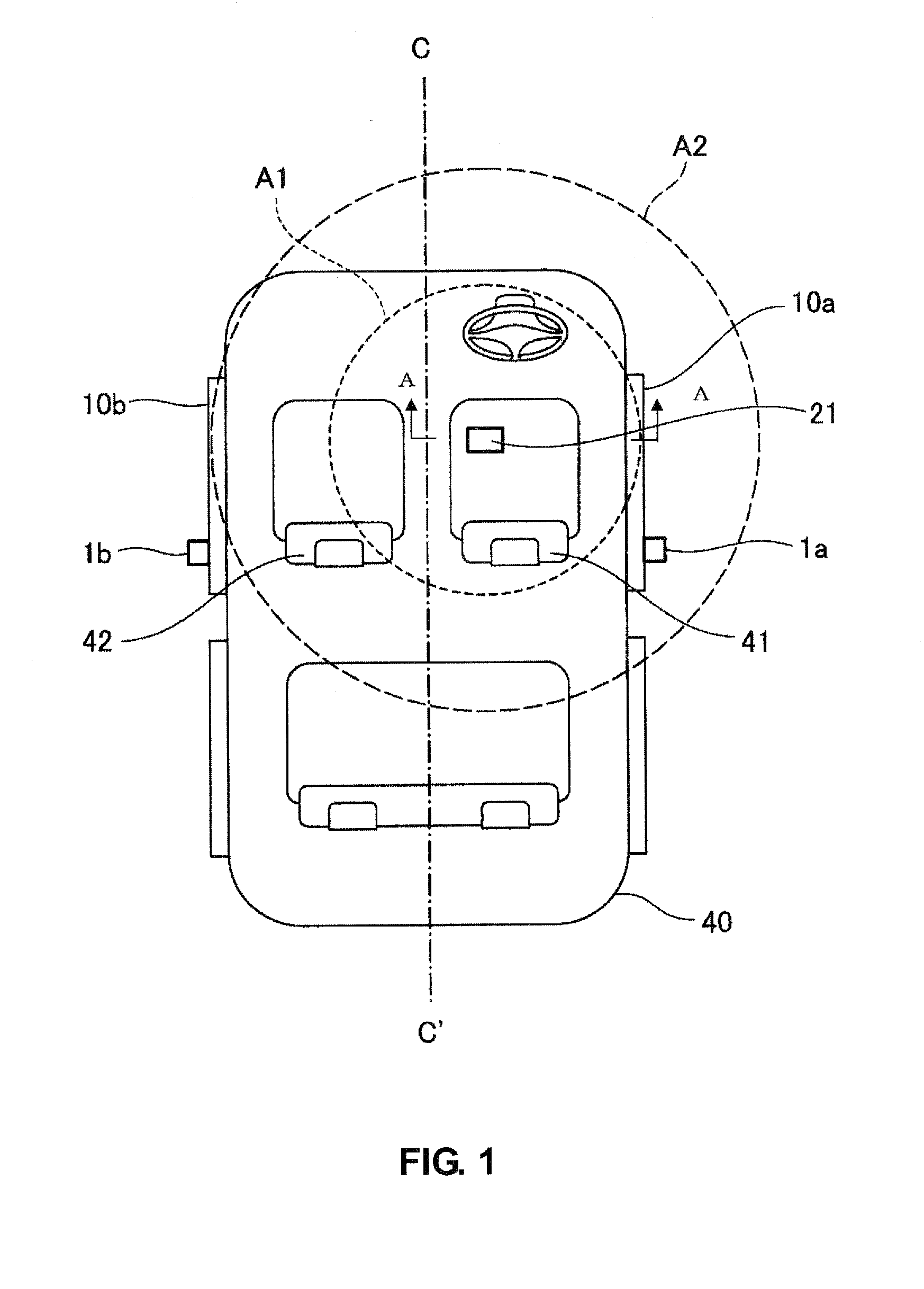
[0034]Hereinafter, a first embodiment of the smart keyless entry system of the present invention will be described. A basic concept of the present invention will be described referring to FIG. 1 in the first embodiment. FIG. 1, which is a schematic plan view of the vehicle compartment of the vehicle, shows the layout and the output range of a switching transmitting antenna of vehicle-inside transmitting antennas. FIG. 7 is a perspective view taken along line A-A of FIG. 1.

[0035]In the present embodiment, a vehicle-inside transmitting antenna 21 to transmit the request signal in the vehicle compartment is disposed below the driver's seat 41, which is off the center line C-C′ on the right side of the vehicle compartment. The vehicle-inside transmitting antenna 21 is fixed to a floor panel FP below the driver's seat 41 via a bracket BRK. The onboard device (not illustrated) is configured so as to switch the output strength of the request signal transmitted by the switching transmitter ...

embodiment 2

[0041]Next, the smart keyless entry system of a second embodiment of the present invention will be described. At first, the basic constitution of the smart keyless entry system according to the present invention will be described referring to FIG. 2. FIG. 2 is a block diagram to show the smart keyless entry system of the present embodiment.

[0042]As shown in FIG. 2, the smart keyless entry system of the present embodiment comprises the access switches 1a, 1b which are provided at outer faces of both-side doors of the vehicle, an onboard device 2 operative transmit the request signal of the LF band in response to operation of the access switches 1a, 1b, and the portable device 3 operative to transmit the receipt-acknowledgement signal of the UHF band in response to receiving the request signal. Herein, in FIG. 2, the access switch 1a provided at the outer face of the door on the side of the driver's seat is indicated as “right access switch,” and the access switch 1b provided at the o...


PUM


Abstract

A transmitting antenna to transmit a request signal in a vehicle compartment is disposed off the center line of the vehicle compartment in a vehicle width direction. The output strength of the request signal transmitted by the transmitting antenna is switched in such a manner that a receivable output range of the request signal by a portable device reaches one of both doors which is equipped with one of access switches which has been operated. Accordingly, it can be properly recognized whether the portable device is located inside the vehicle compartment or outside the vehicle compartment even if the transmitter to transmit the request signal in the vehicle compartment is disposed off the center line of the vehicle compartment in the vehicle width direction.

Description

BACKGROUND OF THE INVENTION[0001]The present invention relates to a smart keyless entry system, and more specifically relates to a smart keyless entry system in which a transmitter of an onboard device is disposed at a specified position which is off the center line of a vehicle compartment in a vehicle width direction.[0002]The smart keyless entry system of the vehicle has been widely used in these days. A portable device of the smart keyless entry system performs the role of a conventional mechanical key. For example, when a card-shaped portable device is carried in a pocket or a bag, a door lock / unlock, an engine start and the like can be operated without using the key. In order to perform such a function, the vehicle is equipped with an onboard device operative to transmit a request signal in response to operations of access switches provided at outer faces of doors. The portable device transmits a receipt-acknowledge signal, such as an ID signal, in response to the request sign...

Claims


Application Information

Patent Timeline
Patent Type & Authority Patents(United States)
IPC IPC(8): G08B29/00B60R25/01B60R25/24B60R25/30B60R25/31E05B49/00
CPCB60R25/245B60R25/246G07C9/00309G07C2009/00333G07C2009/00523G07C2209/63
Inventor HAMADA, YASUSHI
Owner MAZDA MOTOR CORP
Learn More