
Optical measurement arrangement

a measurement arrangement and optical technology, applied in the field of optical measurement arrangement, can solve the problems of introducing errors into the power correction of intensity signal, complex process, and laborious process of urine specimens

Active Publication Date: 2012-11-13
POCARED DIAGNOSTICS
View PDF36 Cites 17 Cited by
  • Summary
  • Abstract
  • Description
  • Claims
  • Application Information

AI Technical Summary

Problems solved by technology

In general, current-day practice for identifying micro-organisms, e.g., bacteria in urine specimens involves a complex, lengthy and expensive process for identifying and specifying micro-organisms in microbiology labs.
This entire process generally takes 11 steps and 50 hours to obtain specimen results and the process is labor intensive.
Thus, a correction to the intensity of the signal represented by the first split illumination beam based on the intensity of the second split beam being detected by the detector assembly of the prior art optical measurement arrangements, will introduce errors into the power correction to the intensity signal of the illumination beam of these optical measurement arrangements.

Method used


Image

  • Optical measurement arrangement
  • Optical measurement arrangement
  • Optical measurement arrangement

Examples


Embodiment Construction

[0023]The present invention will be described with reference to the accompanying drawings where like reference numbers correspond to like elements. The optical measurement arrangement of the present invention may be used in the optical analyzer described in a system for conducting the identification and quantification of bacteria in urine samples such as that disclosed in the above-discussed WIPO Publication No. WO 2009 / 049171, filed October 10, 2008, which is incorporated herein by reference in its entirety.

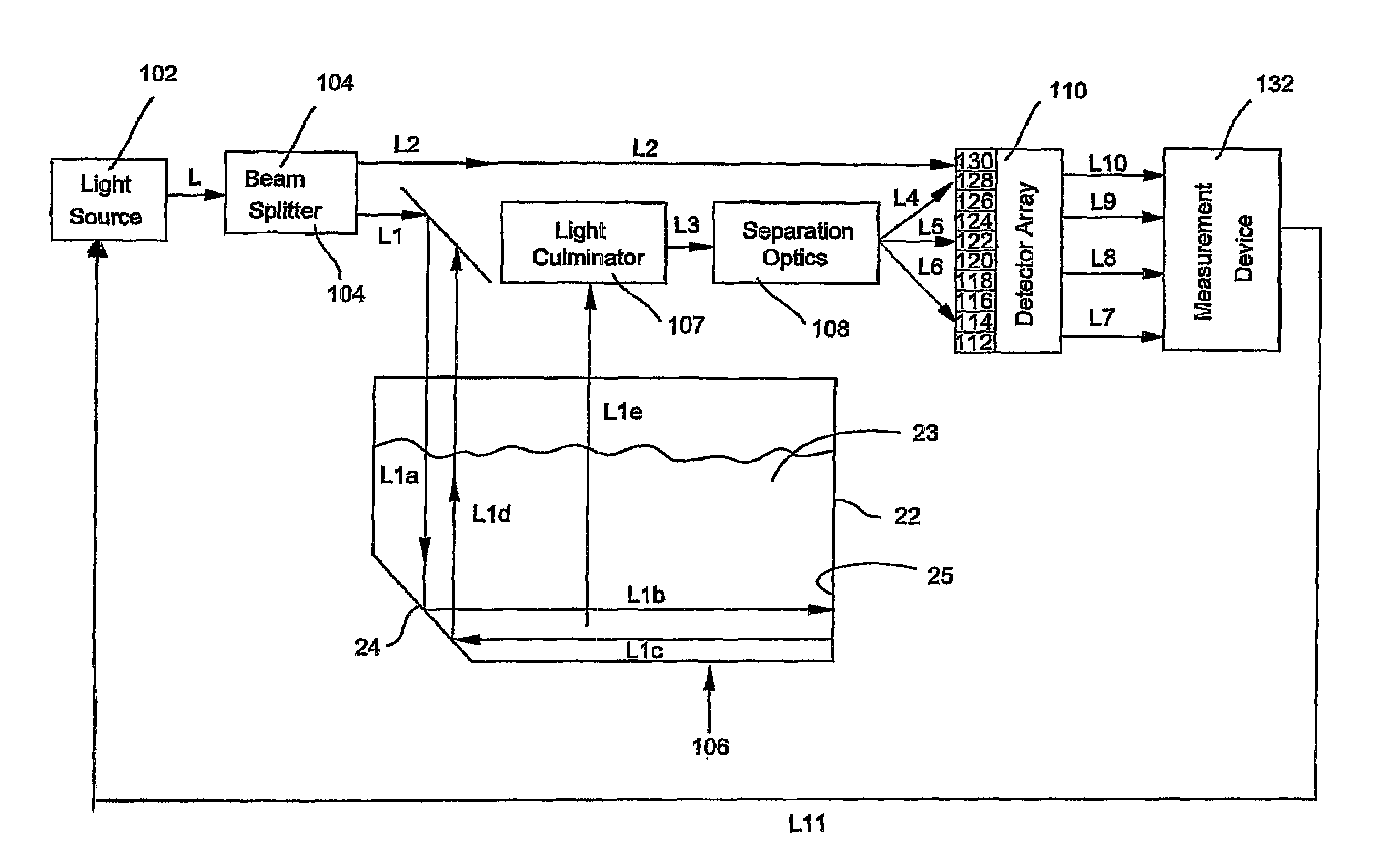
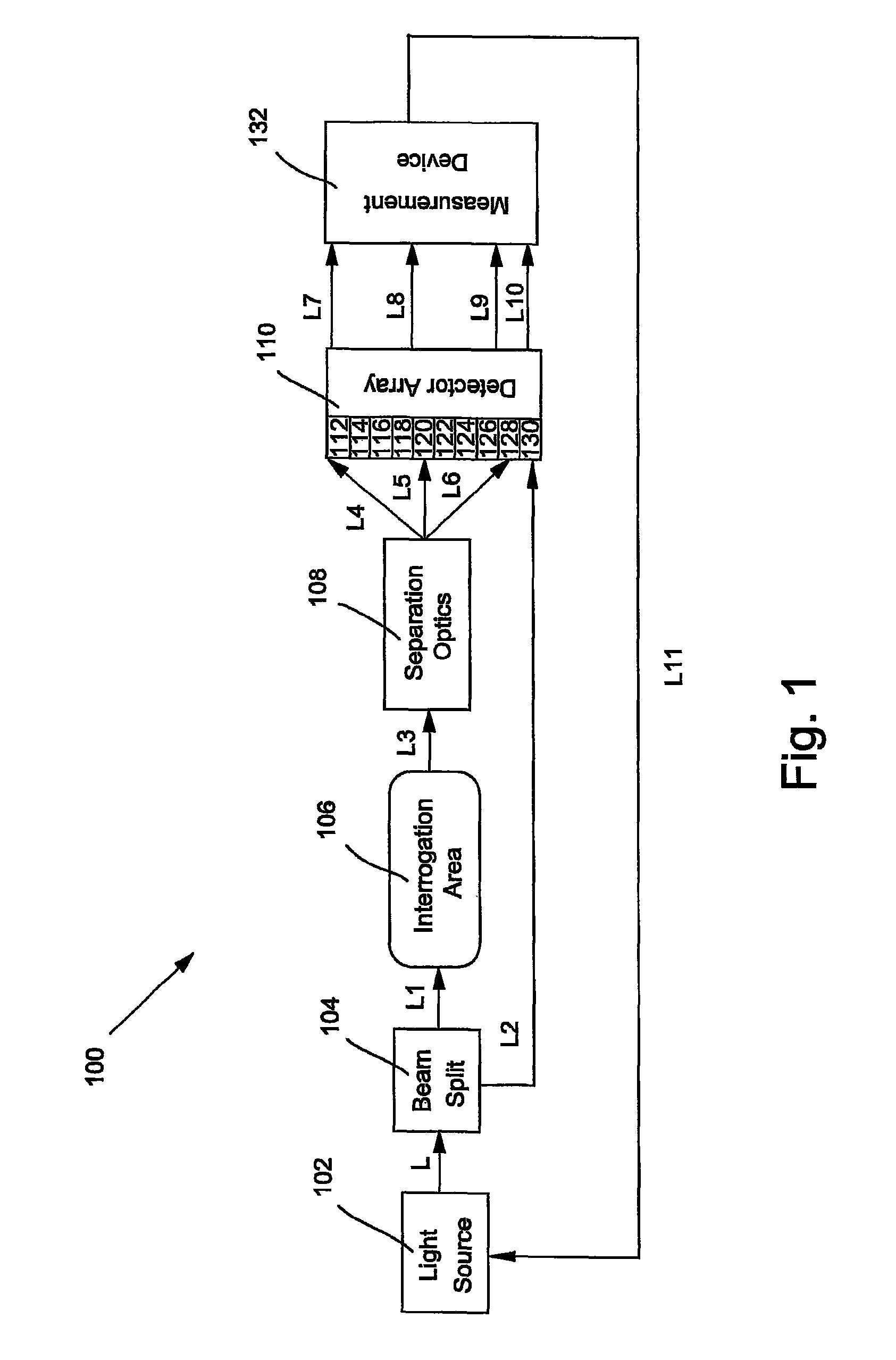
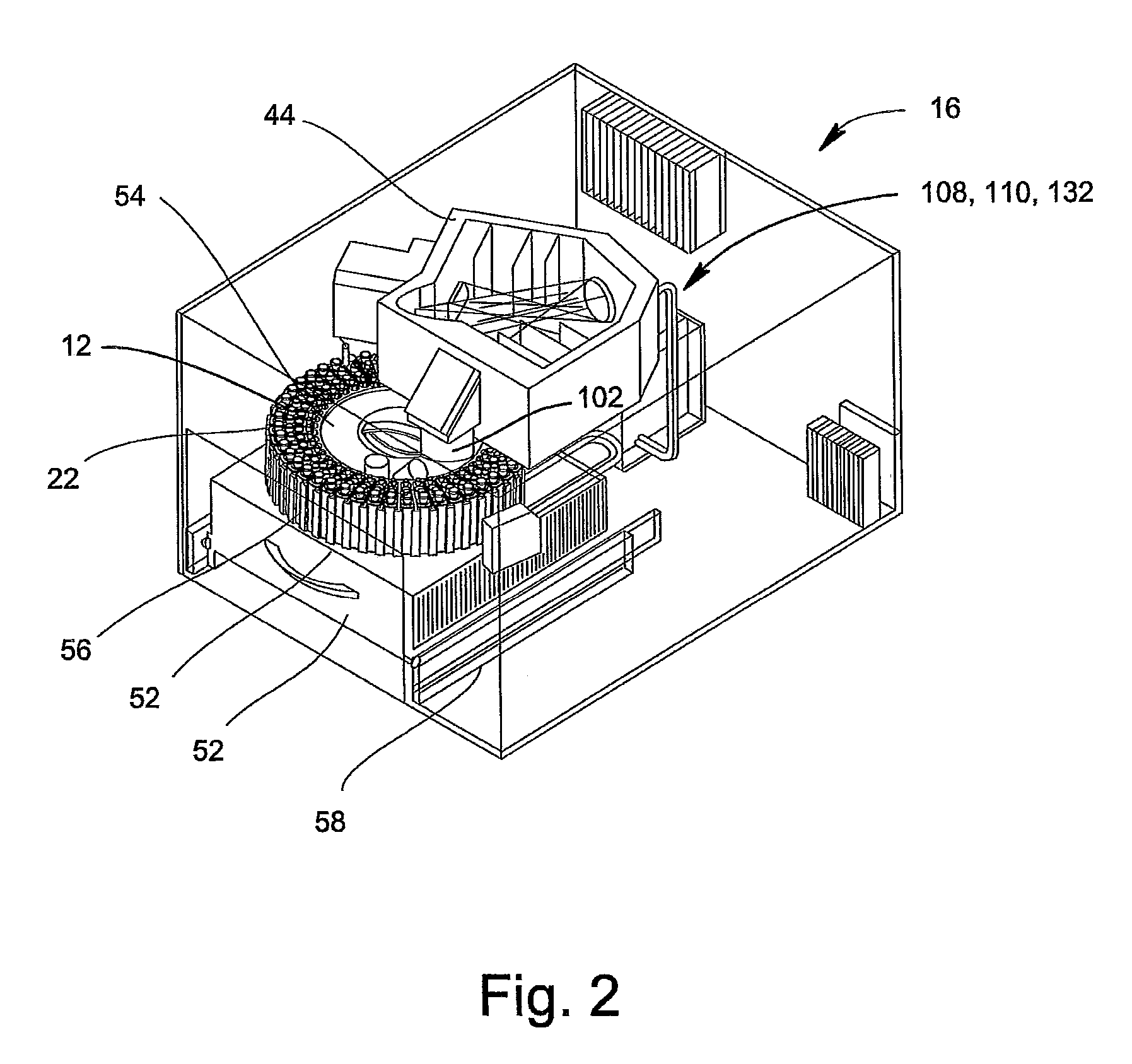
[0024]As stated hereinabove, FIG. 1 is a schematic illustrating an optical measurement arrangement of the present invention which optionally may be used in the system for conducting the identification of bacteria in urine samples. In this instance, the optical measurement arrangement 100 may be used in the optical analyzer 16 shown in FIG. 2 and further discussed below. This optical analyzer is also shown and discussed in detail in WIPO Publication No. WO 2009 / 049171.

[0025]As sh...


PUM

PropertyMeasurementUnit
volumeaaaaaaaaaa
volumeaaaaaaaaaa
light intensityaaaaaaaaaa

Abstract

A method and device for enhancing the power correction of optical measurements in an optical measurement arrangement, the steps including: providing a light source for producing a light beam; splitting the light beam into two beams; directing a first split light beam through an interrogation area and into an optics separation device; directing the light beams from the optics separation device and a second split light beam representing the intensity of the illumination of the main light beam of the light source into cells of a detector array; measuring and assessing the information obtained in the cells; and using this information to calculate the corrected value for the cells receiving the light beams from the optics separation device in order to adjust the power for the intensity of the light beam of the light source and / or to correct the intensity of the light beams from the interrogation area.

Description

CROSS REFERENCE TO RELATED APPLICATIONS[0001]The present cross-reference application claims priority to Provisional Application No. 61 / 150,430, entitled “Optical Measurement Arrangement”, filed on Feb. 6, 2009, which is herein incorporated by reference in its entirety.BACKGROUND OF THE INVENTION[0002]1. Field of the Invention[0003]This invention relates to an optical measurement arrangement which includes a detector array assembly having a plurality of detector elements. More specifically, the invention relates to an optical measurement arrangement which corrects the power changes occurring in the optical measurement arrangement when performing the optical measurement of a signal which is a result of a light illumination. The optical measurement arrangement of the invention may find particular application in an optical analyzer for analyzing urine samples.[0004]2. Description of Related Art[0005]In general, current-day practice for identifying micro-organisms, e.g., bacteria in urin...

Claims


Application Information

Patent Timeline
Patent Type & Authority Patents(United States)
IPC IPC(8): G01J1/32G01N21/03G01N33/539G01N35/02
CPCG01J1/32G01J3/42G01N21/031G01N21/253G01J2003/2866G01N2201/0415G01N2201/0469G01N2201/0692
Inventor INGBER, GAL
Owner POCARED DIAGNOSTICS
Learn More