Eureka AIR delivers breakthrough ideas for toughest innovation challenges, trusted by R&D personnel around the world.

Method and apparatus for tissue morcellation

a tissue and morcellation technology, applied in the field of minimally invasive surgery, can solve the problems of reducing effectiveness and life, unable to visualize tissue, and unable to achieve rotational cutting, so as to facilitate tissue cutting, facilitate rotational cutting, and reduce the diameter of the tissu

Inactive Publication Date: 2012-11-13
APPL MEDICAL RESOURCES CORP
View PDF18 Cites 36 Cited by
  • Summary
  • Abstract
  • Description
  • Claims
  • Application Information

AI Technical Summary

Benefits of technology

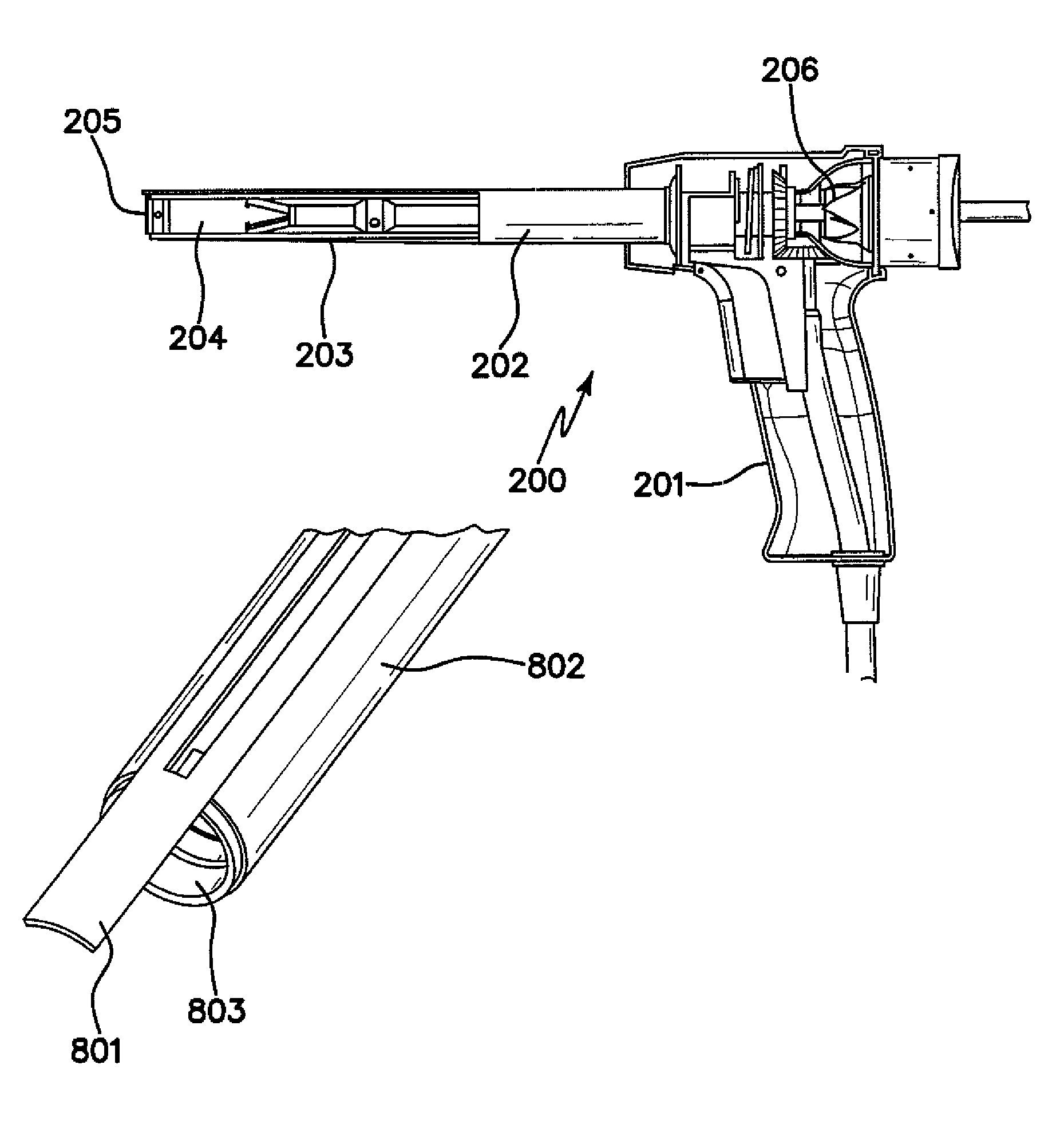
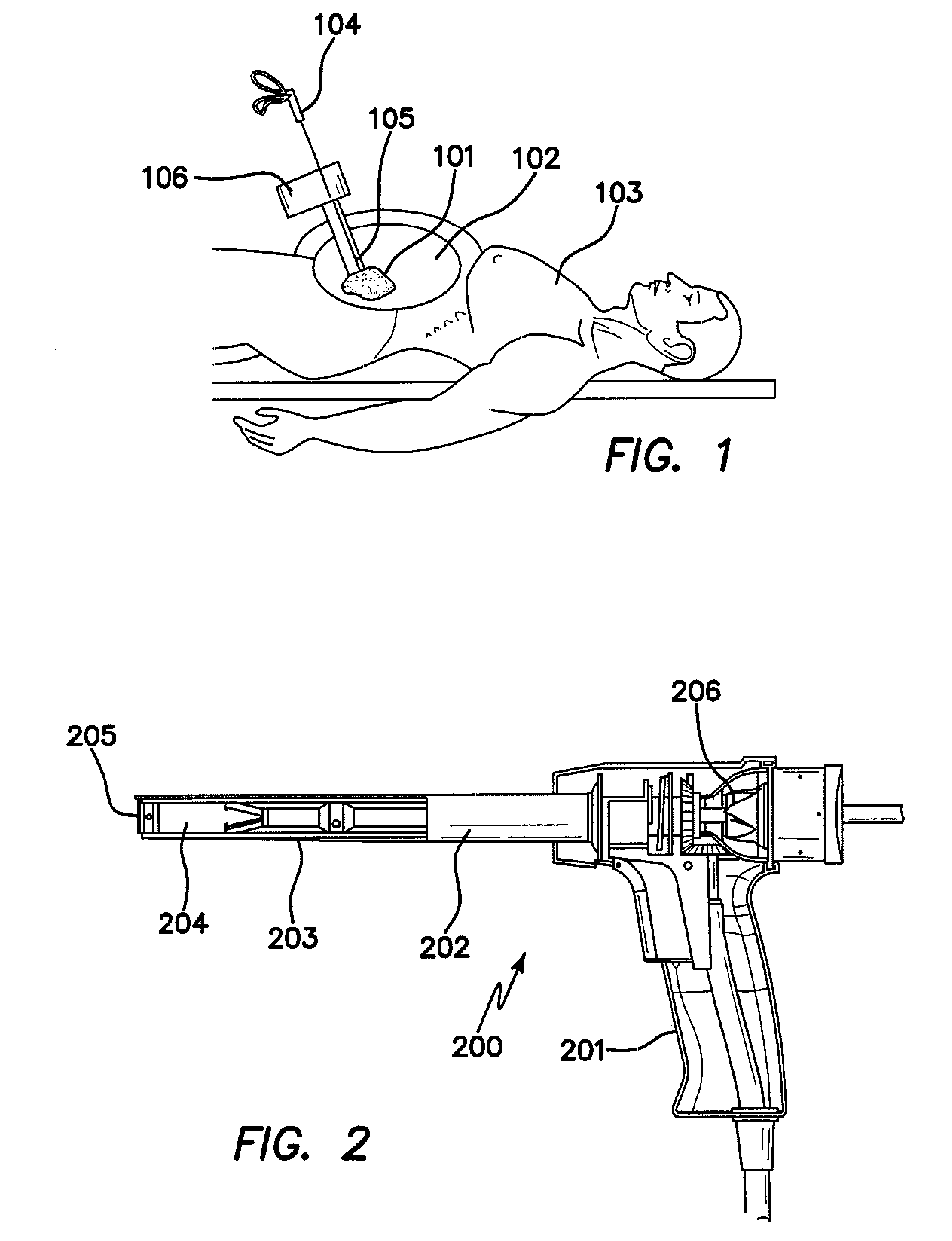
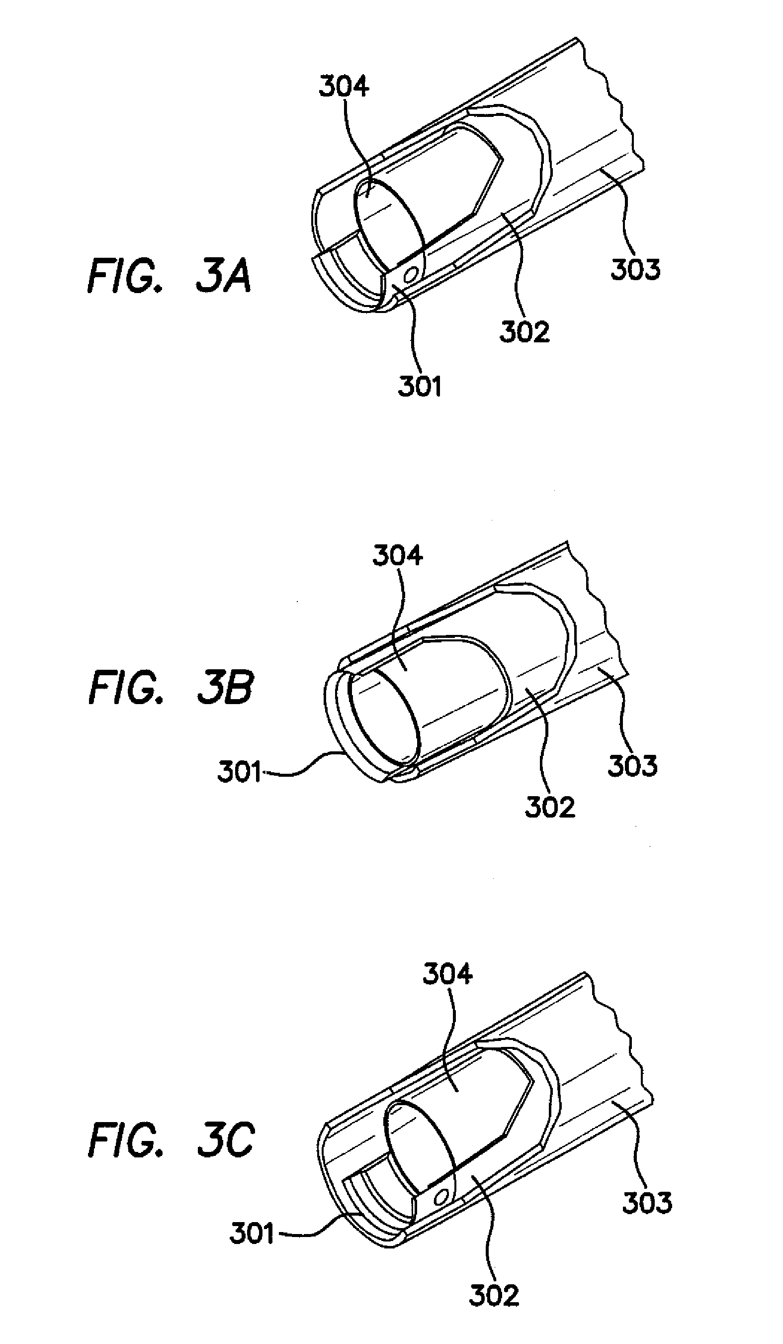
[0014]The tissue morcellation device may include a third, inner cylindrical tube that is transparent and positioned concentrically within a lumen of the second, inner tube. The third, inner tube is stationary in relation to the first, outer tube. The second, inner tube may have a metallic cutting ring mounted on a distal portion of the second, inner tube. The metallic cutting ring has a sharpened distal edge that forms the sharpened distal edge of the second, inner tube. Alternatively, the distal edge of the second, inner tube is sharpened to provide the sharpened distal edge of the second, inner tube. The tissue morcellation device may include a vibrating element for facilitating the rotational cutting performed by the second, inner tube. The second, inner tube may be adapted to oscillate rotationally about the longitudinal axis in relation to the first, outer tube. If adapted to oscillate, the second, inner tube reversibly rotates between 10° and 30° about the longitudinal axis. When the third, inner cylindrical tube is present, the second, inner tube oscillates between the first, outer tube and the third, inner tube. Alternatively, the second, inner tube and the third, inner tube may be adapted to oscillate in opposite directions. The tissue morcellation device may include a vibrating element for facilitating the oscillation cutting performed by the second, inner tube and the third, inner tube. The sharpened edge at the distal end of each of the second, inner tube and third, inner tube may be serrated. The tissue morcellation device may include a seal for sealing against surgical devices inserted through the tissue morcellation device. The tissue morcellation device may also include a tenaculum having a shaft and a spacer positioned concentrically on the shaft. The outer diameter of the spacer provides a loose fit between the spacer and a lumen wall of the second, inner tube, or the third, inner tube, when provided, to prevent the shaft of the tenaculum from touching the sharpened distal edge of the second, inner tube during manipulation of the tenaculum. The tenaculum may include a handle that is configured to supply a rotating motion along an axis of the connecting shaft. In this manner, tissue that is engaged with the cutting, distal end of the second, inner tube is twisted by the rotary action of the tenaculum so that the diameter of the tissue is reduced for easy withdrawal from within the tissue morcellation device. The tissue morcellation device may include a vibration source adapted to vibrate the second, inner tube. The vibration source is adjusted to facilitate tissue cutting with the second, inner tube with no rotational movement of the second, inner tube. The tissue morcellation device may also include a hand-piece that has a mechanical gear mechanism for generating rotation of the second, inner tube.

Problems solved by technology

Although morcellators based on cylindrically rotating cutting tubes enable much faster and more practical tissue removal than tissue “chipping” devices, they do show some practical and functional disadvantages.
One drawback is that the tissue cannot be visualized as it is being pulled into the morcellator.
Another disadvantage of this arrangement is that both the shaft and the opened jaws of the grasper or tenaculum may damage the edge of the cylindrical cutting blade during manipulation, dramatically reducing its effectiveness and life.
A functional disadvantage of the rotating cylindrical cutting tube design is that tissue can rotate along the longitudinal axis of the cylindrical cutting tube.
Another practical disadvantage of current cutting tube arrangements in terms of continuous tissue removal is that tissue being fed into the morcellator in a rotating fashion, which allows peeling of the tissue, can overspill beyond the opening of the morcellator.

Method used


Image

  • Method and apparatus for tissue morcellation
  • Method and apparatus for tissue morcellation
  • Method and apparatus for tissue morcellation

Examples


Embodiment Construction

[0031]Unless defined otherwise, all technical and scientific terms used herein have the same meaning as commonly understood to one of ordinary skill in the art to which this invention belongs. Although any methods, devices and materials similar or equivalent to those described herein can be used in the practice or testing of the invention, the preferred methods, devices and materials are now described.

[0032]All publications mentioned herein are incorporated herein by reference for the purpose of describing and disclosing, for example, the structures and / or methodologies that are described in the publications which might be used in connection with the presently described invention. The publications discussed above and throughout the text are provided solely for their disclosure prior to the filing date of the present application. Nothing herein is to be construed as an admission that the inventors are not entitled to antedate such disclosure by virtue of prior invention.

[0033]The fol...


PUM


Abstract

The invention relates to a tissue morcellator for minimally invasive surgery. The morcellator has a metallic cutting ring mounted on a visually transparent hollow cylinder, which in combination with a visually transparent outer morcellator tube enables a surgeon to visualize the inside of the morcellator shaft for detection of loose tissue fragments in the device. A tenaculum used with the morcellation device has a spacer for preventing contact with the blade. The cutting tube can oscillate, rather than rotate, along the longitudinal axis of the cutting tube. The morcellator utilizes an extendable tissue guide on the outer tube of the morcellator shaft for preventing the tissue from rotating along the longitudinal axis of the morcellator tube. This allows the tissue to be continuously rotated into the morcellator device for continuous peel. The tissue guide can also be fully retracted to allow for coring of the bulk tissue.

Description

CROSS-REFERENCE TO RELATED APPLICATIONS[0001]This application claims the benefits of and priority to U.S. Provisional Patent Application No. 60 / 911,444, filed on Apr. 12, 2007, the disclosure of which is hereby incorporated by reference as if set forth in full herein.FIELD OF THE INVENTION[0002]The present invention relates generally to the field of minimally invasive surgery, and in particular to a method and apparatus for the morcellation and extraction of biological, human tissue through a hollow cylindrical cutting tube that is rotated along its longitudinal axis, preferably configured as a hand-held laparoscopic device. The instrument allows visual observation of the tissue extraction trough the cutting tube. The instrument also incorporates a tissue guide or manipulator that can be extended beyond the distal position of the cutting blade of the tool, preventing both the coring of the tool into the tissue, as well as rotation of the tissue along the longitudinal axis of the mor...

Claims


Application Information

Patent Timeline
Patent Type & Authority Patents(United States)
IPC IPC(8): A61B17/32
CPCA61B17/32002A61B17/32053A61B17/29A61B19/5212A61B2017/00902A61B2017/2948A61B2017/320024A61B2017/320775A61B90/361
Inventor PRAVONG, BOUNPRAVONGVIENGKHAM, KENNIIBECERRA, MATTHEW M.WIXEY, MATTHEW A.YAWATA, HARUYASUJOHNSON, GARY M.FALKENSTEIN, ZORANBRUSTAD, JOHN R.HART, CHARLES C.
Owner APPL MEDICAL RESOURCES CORP
Why Eureka
Eureka Blog
Learn More