
Vertebroplasty all in one mixer

a technology for vertebroplasty and mixer, which is applied in the directions of osteosynthesis devices, prosthesis, transportation and packaging, etc., can solve the problems of difficult mixing and dispensing of powder, noxious and toxic to handle, and increase the working time between mixing and dispensing, so as to facilitate mixing and dispensing and flexible working times

Active Publication Date: 2012-11-13
COOK MEDICAL TECH LLC
View PDF15 Cites 37 Cited by
  • Summary
  • Abstract
  • Description
  • Claims
  • Application Information

AI Technical Summary

Benefits of technology

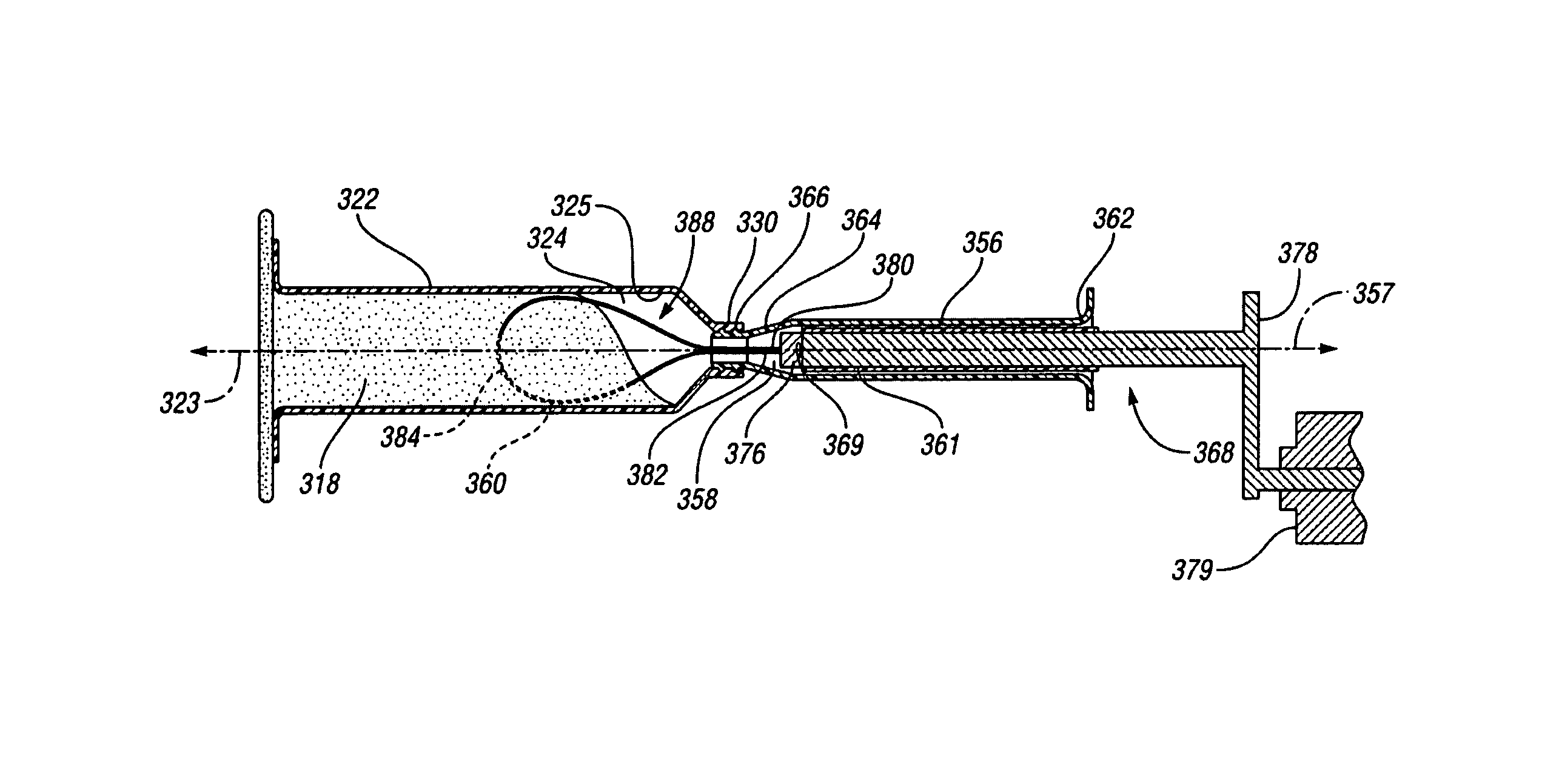
The present invention provides a device, kit, and method for mixing and dispensing bone cement mixture. The device includes an injector housing with two chambers for containing bone cement components, and a mixing element for mixing the components together. The mixing element is either coupled to a stop member or a stop member is slidable within the second chamber. The device also includes a handle for assembly with the injector housing and a needle for advancing the bone cement mixture into the damaged bone of a patient. The invention allows for minimal exposure to noxious vapors and provides more flexible working times for the interventionalist and patient.

Problems solved by technology

These materials have relatively good strength characteristics, but have a number of drawbacks.
As for example with the PMMA based system, one of the components is a liquid monomer methylmethacrylate (MMA), which is noxious and toxic to handle.
The other component, the polymer component PMMA, is a powder that can be difficult to mix thoroughly.
Also, the working time increases between mixing and dispensing because once the mixture is mixed it then needs to be transferred to a syringe for injection into the damaged bone.
Moreover, the working time is limited because the viscosity of the cement constantly increases during mixing, thus making transferring of the mixture to the syringe and injection of the mixture into the damaged bone more difficult.
Often, very high injection pressures and / or large bore needles may be necessary to inject the mixture, especially if it is near the end of the cements working time.

Method used


Image

  • Vertebroplasty all in one mixer
  • Vertebroplasty all in one mixer
  • Vertebroplasty all in one mixer

Examples


Embodiment Construction

[0039]Detailed embodiments of the present invention are disclosed herein. It is understood however, that the disclosed embodiments are merely exemplary of the invention and may be embodied in various and alternative forms. The figures are not necessarily to scale; some figures may be configured to show the details of a particular component. Therefore, specific structural and functional details disclosed herein are not to be interpreted as limiting but merely as a representative basis with the claims and for teaching one skilled in the art to practice of the present invention.

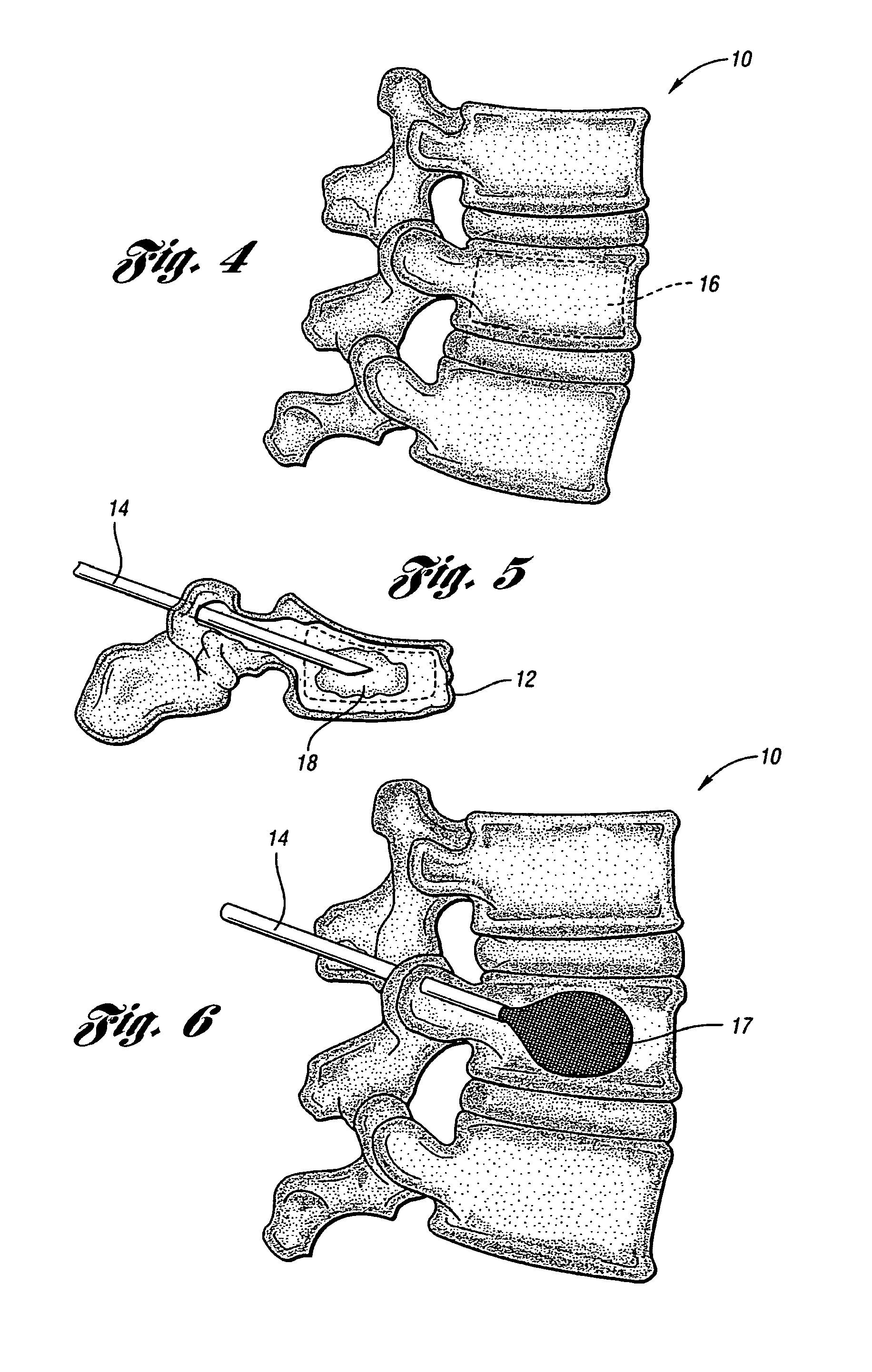
[0040]Examples of the present invention seek to overcome some of the concerns associated with stabilizing and / or repairing the damaged bone of a patient with a bone cement while minimizing toxic effects to both the patient and the interventionalist, and enhancing the ease of handling of the bone cement for both mixing and dispensing into the damaged bone.

[0041]Employing the principles of the present invention is...


PUM

PropertyMeasurementUnit
viscosityaaaaaaaaaa
viscosityaaaaaaaaaa
diameteraaaaaaaaaa

Abstract

In at least one embodiment of the present invention, a device for mixing and dispensing a bone cement mixture is provided. The device comprises an injector housing having a chamber for containing a first and a second bone cement component and a second housing having a chamber for containing a flexible wire mixing element. A plunger actuates within the chamber of the second housing to transfer the wire mixing element to the injector housing for mixing the first and second bone cement components to form the bone cement mixture. The plunger rotates the wire mixing element to mix the bone cement mixture. Thereafter, the wire mixing element is withdrawn from the injector housing and the injector housing is assembled with an injector handle. A plunger coupled to the injector handle advances through the injector chamber to dispense the bone cement mixture from the device.

Description

BACKGROUND OF THE INVENTION[0001]1. Field of the Invention[0002]The present invention relates to a device, a kit and a method for mixing and dispensing a bone cement mixture.[0003]2. Description of Related Art[0004]There is a clinical need to fill and stabilize damaged bones of patients, such as for example, filling defects in collapsed vertebra of patients suffering from severe back pain caused by osteoporosis, metastatic tumors or back injuries. Currently, these defects are repaired using multi-component bone cements that are mixed in open containers, transferred to a device and injected into the damaged bone where the mixture chemically reacts or cures to form a solid support structure.[0005]The most widely used bone cements are based on polymethylmethacrylate (PMMA) and hydroxyapatite. These materials have relatively good strength characteristics, but have a number of drawbacks. These cements are a two-part chemically reactive system and have approximately five to ten minutes of...

Claims


Application Information

Patent Timeline
Patent Type & Authority Patents(United States)
IPC IPC(8): A61B17/58
CPCA61B17/8819A61B17/8822B01F7/0005B01F7/00566B01F13/002B01F13/0023B01F15/0201B01F15/0203B01F15/0225B01F15/0237B01F15/0279B01F27/054B01F27/119B01F33/50112B01F33/5011B01F35/712B01F35/7163B01F35/7174B01F35/754251B01F35/7179
Inventor VALAIE, ARMAN H.
Owner COOK MEDICAL TECH LLC
Learn More