Light emitting diode system

Inactive Publication Date: 2012-11-13
SAXON THOMAS JASON +1
View PDF6 Cites 336 Cited by
  • Summary
  • Abstract
  • Description
  • Claims
  • Application Information

AI Technical Summary

Benefits of technology

[0010]To attain this, the present invention essentially comprises a light emitting diode light system. The light emitting diode light system for boat / trailer showers is for illuminating a showering area in a safe, convenient and economical manner. A light emitting diode may be referred to as an LED.
[0020]It is another object of the present invention to provide a new and improved light emitting diode light system which may be easily and efficiently manufactured and marketed.
[0021]It is further object of the present invention to provide a new and improved light emitting diode light system which is of durable and reliable constructions.
[0022]An even further object of the present invention is to provide a new and improved light emitting diode light system which is susceptible of a low cost of manufacture with regard to both materials and labor, and which accordingly is then susceptible of low prices of sale to the consuming public, thereby making such light emitting diode light system economically available to the buying public.
[0023]Even still another object of the present invention is to provide a light emitting diode light system for lighting up a showering area in a safe, convenient and economical manner.

Problems solved by technology

While prior light systems fulfill their respective, particular objectives and requirements, they do not describe a light emitting diode light system that allows for illuminating a showering area of a boat or trailer in a safe, convenient and economical manner.

Method used


Image

  • Light emitting diode system
  • Light emitting diode system
  • Light emitting diode system

Examples


Embodiment Construction

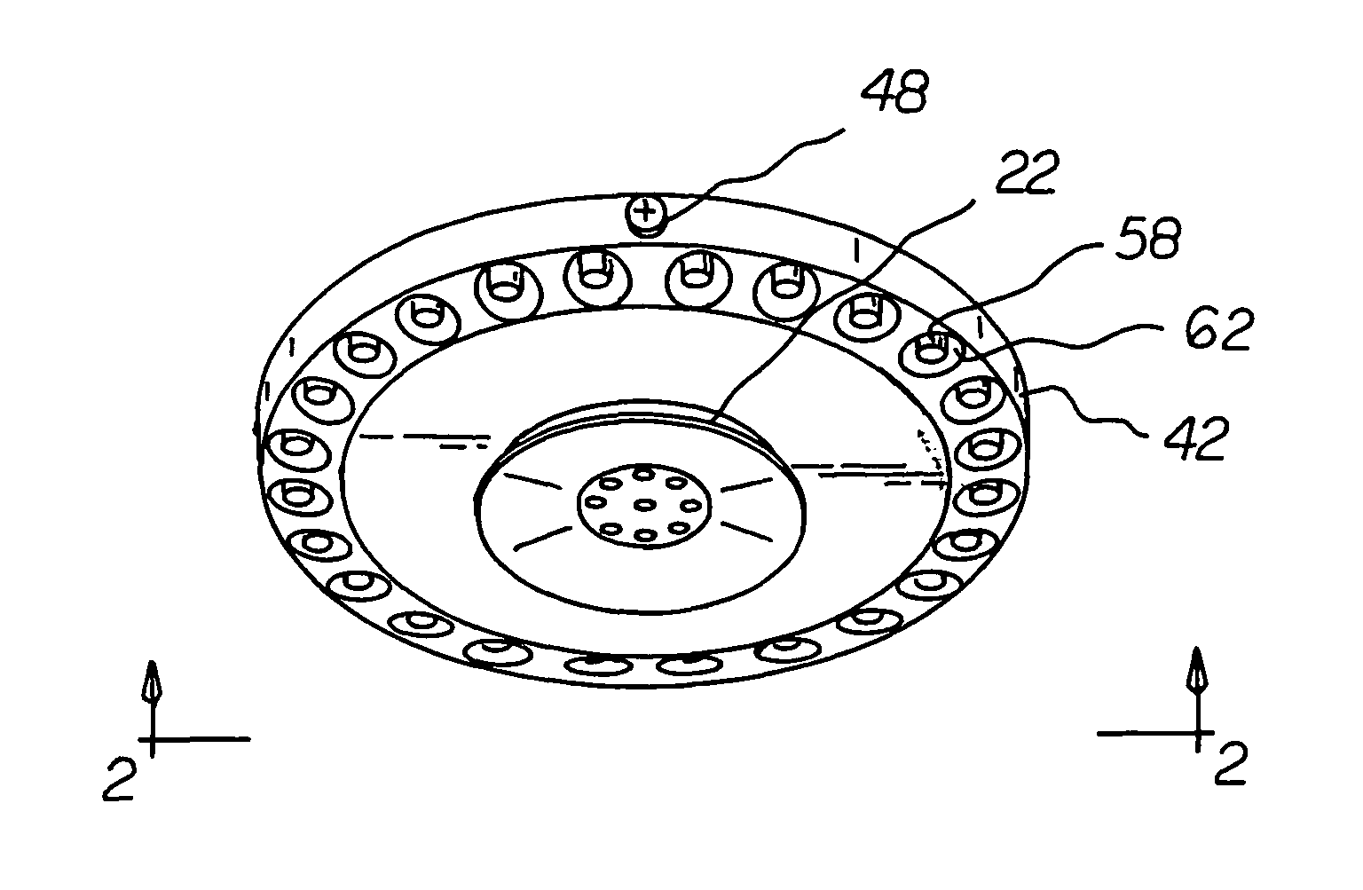
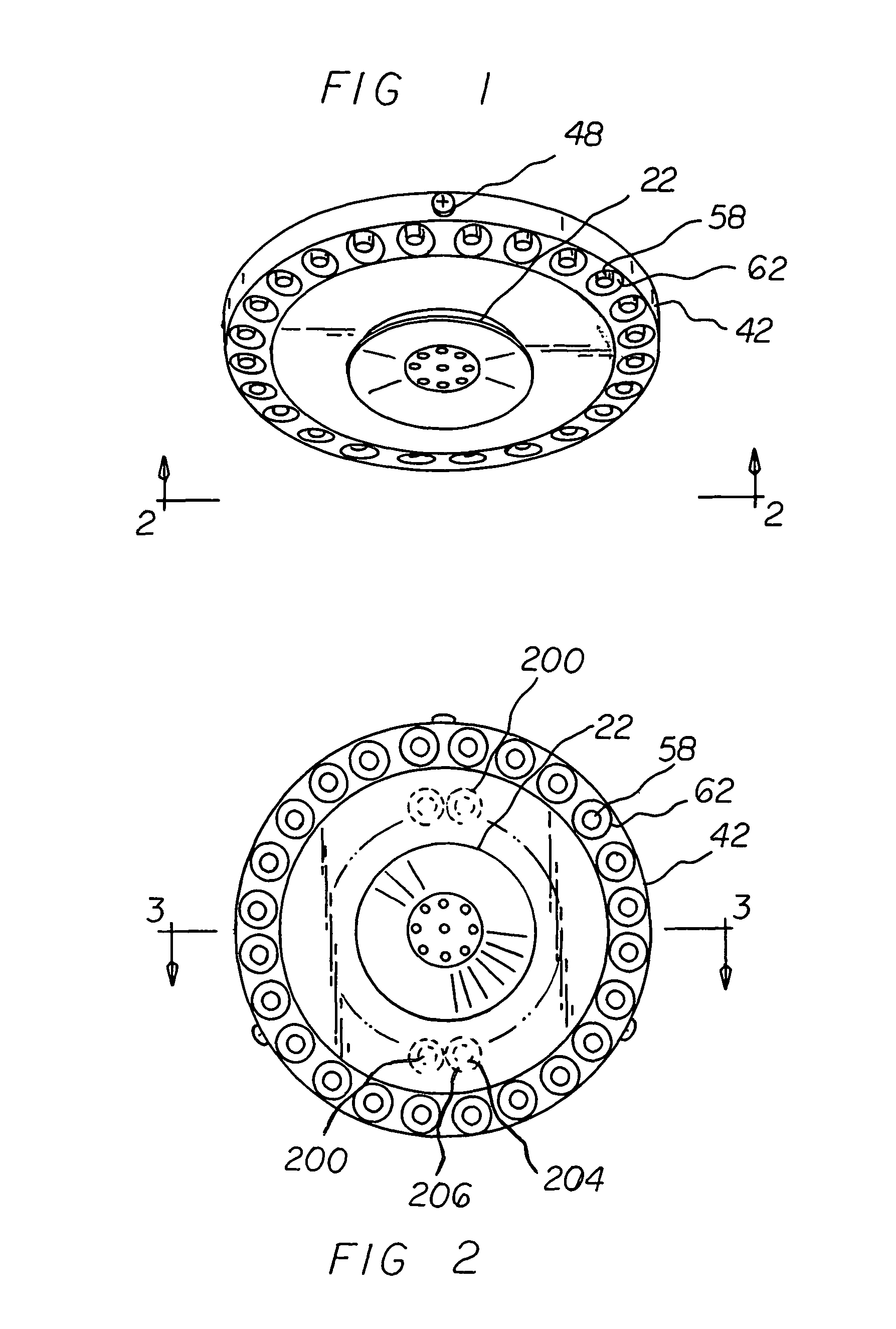
[0034]With reference now to the drawings, and in particular to FIG. 1 thereof, the preferred embodiment of the new and improved light emitting diode light system embodying the principles and concepts of the present invention and generally designated by the reference numeral 10 will be described.

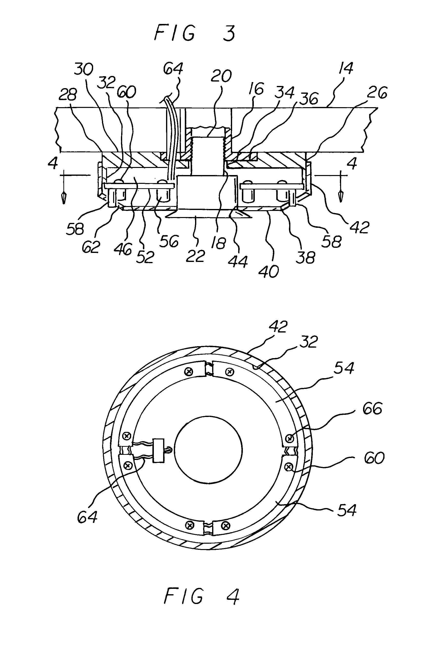
[0035]The present invention, the light emitting diode light system 10 is comprised of a plurality of components. Such components in their broadest context include a housing, an annular printed circuit board and a plurality of light emitting diodes. Such components are individually configured and correlated with respect to each other so as to attain the desired objective.

[0036]The light emitting diode light system 10 for boat / trailer showers is for illuminating a showering area in a safe, convenient and economical manner. A light emitting diode may be referred to as an LED.

[0037]First provided is a showering area having a ceiling 14 with a hole and a water pipe 16 terminating beneath the hole....


PUM


Abstract

A housing has an upper component formed of an upper plate and a periphery. The upper plate has an upper central aperture. The housing has a lower component formed of a lower plate and a periphery. The lower plate has a lower central aperture. An annular printed circuit board is positioned within the housing. A plurality of light emitting diodes are secured to the printed circuit board and extend downwardly therefrom. A plurality of equally spaced small apertures in the lower plate of the lower component each receive one of the light emitting diodes for providing light.

Description

RELATED APPLICATION[0001]This application is based upon and claims the priority of U.S. Provisional Patent Application Ser. No. 61 / 206,772 filed Feb. 4, 2009 the subject matter of which is incorporated herein by reference.BACKGROUND OF THE INVENTION[0002]1. Field of the Invention[0003]The present invention relates to a light emitting diode light system and more particularly pertains to illuminating a showering area of a boat or trailer in a safe, convenient and economical manner.[0004]2. Description of the Prior Art[0005]The use of light systems is known in the prior art. More specifically, light systems previously devised and utilized for the purpose of illuminating a showering area are known to consist basically of familiar, expected, and obvious structural configurations, notwithstanding the myriad of designs encompassed by the crowded prior art which has been developed for the fulfillment of countless objectives and requirements.[0006]While prior light systems fulfill their resp...

Claims


Application Information

Patent Timeline
IPC IPC(8): A47K3/022A47K3/28
CPCF21V33/004B05B1/18B05B15/00F21Y2101/02F21Y2115/10
Inventor SAXON, THOMAS JASONSAXON, HOLLY HOLLEMAN
Owner SAXON THOMAS JASON
Why Eureka
Try Eureka