Outlet covering system

Inactive Publication Date: 2002-10-01
KESTER BILLIE JO M +1
View PDF15 Cites 64 Cited by
  • Summary
  • Abstract
  • Description
  • Claims
  • Application Information

AI Technical Summary

Benefits of technology

It is another object of the present invention to provide a new outlet covering system which may be easily and efficiently manufactured and marketed.
It is a further object of the present invention to provide a new outlet covering system which is of a durable and reliable construction.
An even further object of the present invention is to provide a new outlet covering system which is susceptible of a low cost of manufacture with regard to both materials and labor, and which accordingly is then susceptible of low prices of sale to the consuming public, thereby making such outlet covering system economically available to the buying public.
Still yet another object of the present invention is to provide a new outlet covering system that restricts access to an outlet by a individual such as a child who may be injured by the outlet.
Even still another object of the present invention is to provide a new outlet covering system that that can audibly alert an individual in a supervisory position that another individual is near the outlet. The present invention also provides light in an immediate vicinity in order to allow a user to find their way around in a dimly light or dark area.

Problems solved by technology

While these devices fulfill their respective, particular objectives and requirements, the aforementioned patents do not disclose a new outlet covering system.

Method used


Image

  • Outlet covering system
  • Outlet covering system
  • Outlet covering system

Examples


Embodiment Construction

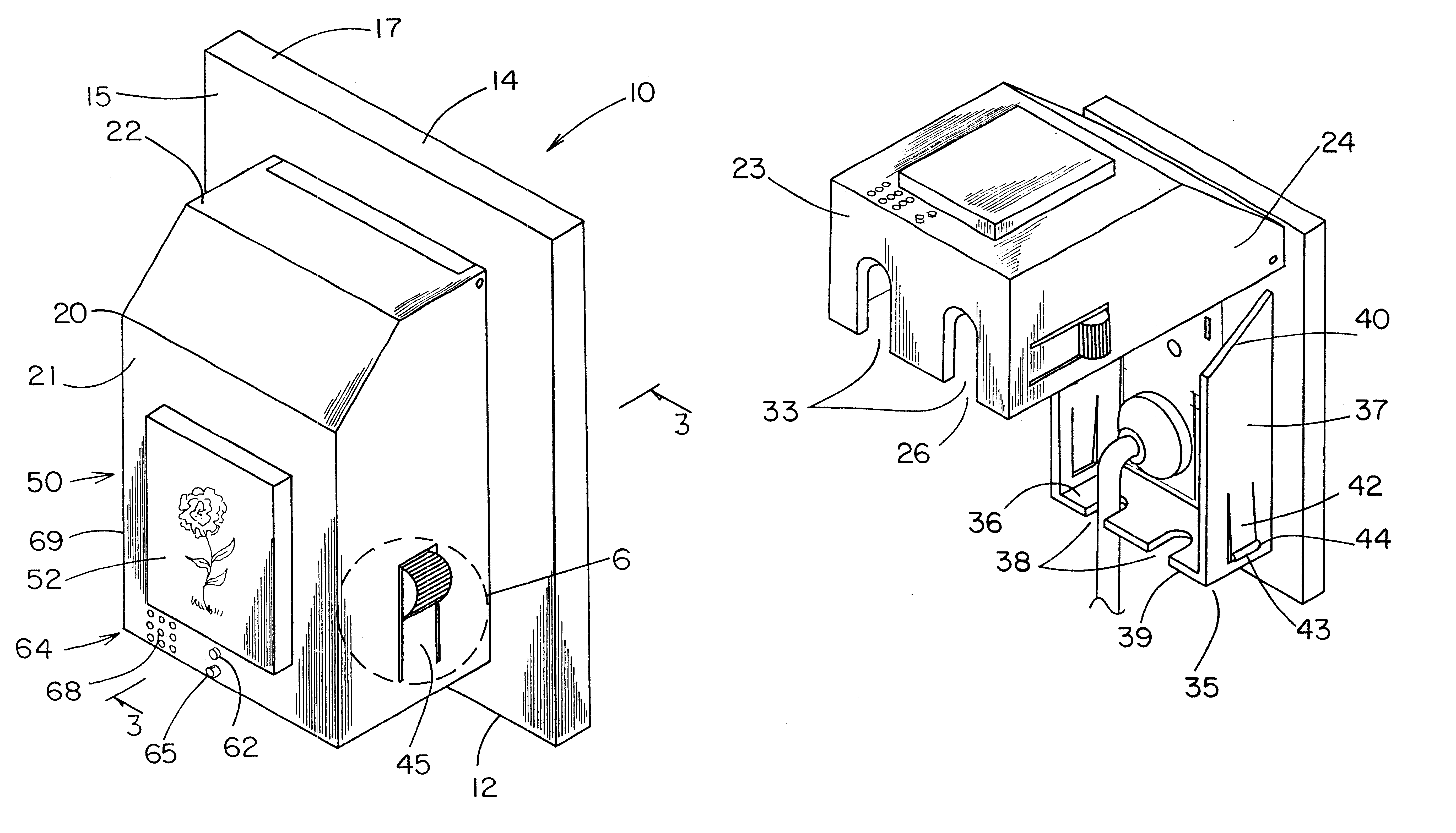
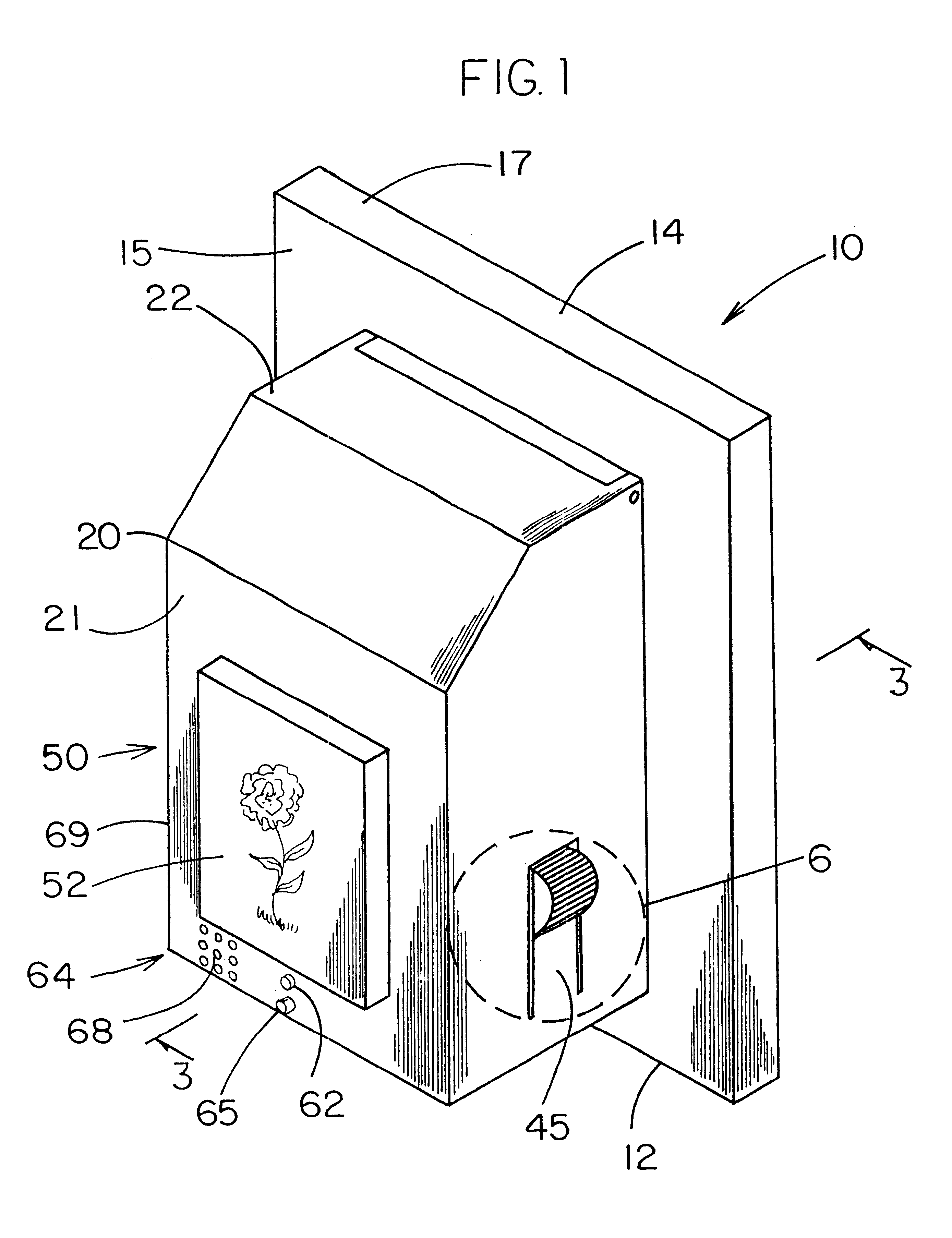
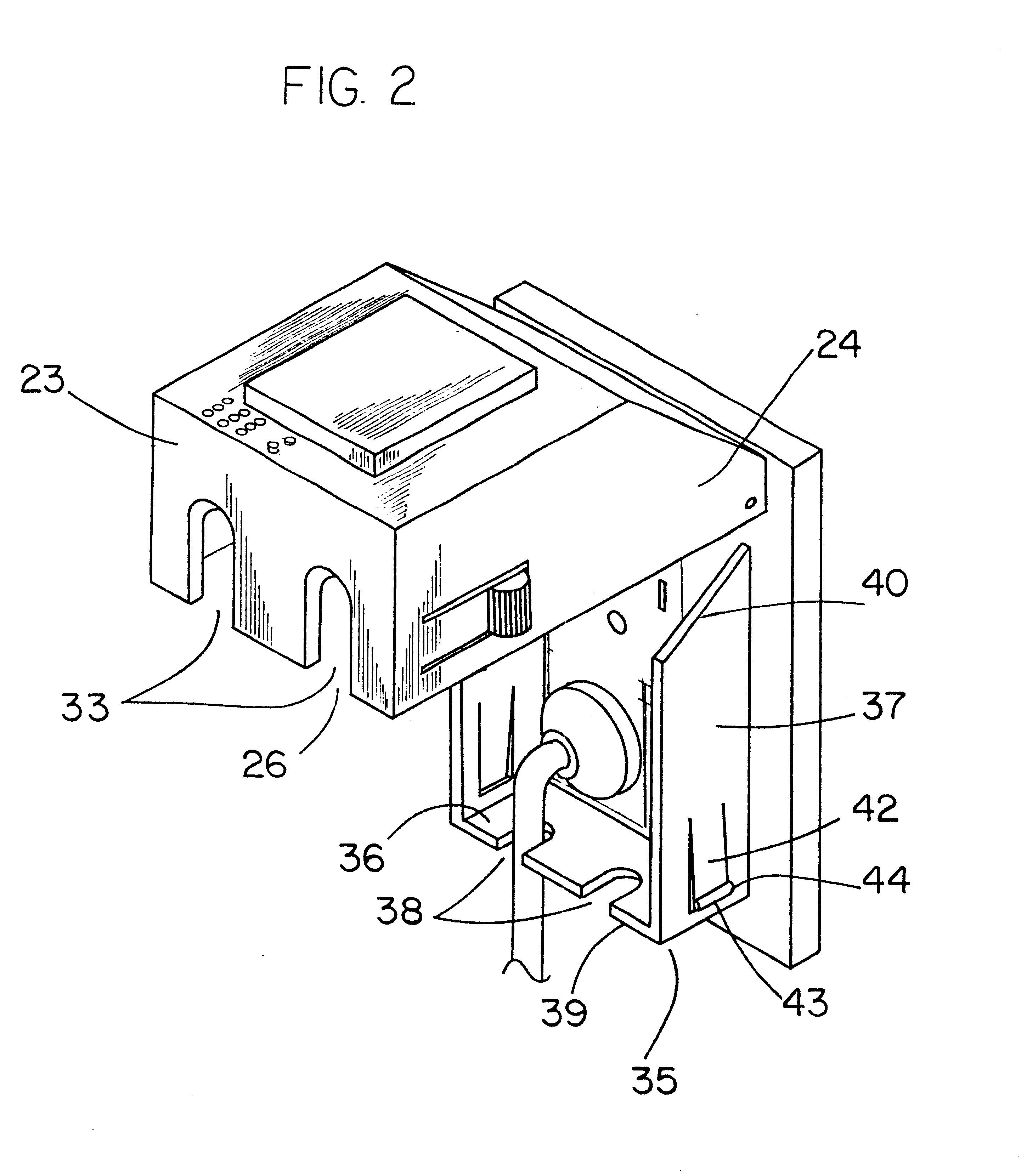
With reference now to the drawings, and in particular to FIGS. 1 through 8 thereof, a new outlet covering system embodying the principles and concepts of the present invention and generally designated by the reference numeral 10 will be described.

As best illustrated in FIGS. 1 through 8, the outlet covering system 10 generally comprises an enclosure 12 for covering the outlet. The enclosure 12 is mountable to the wall surface includes having the outlet. The enclosure 12 preferably comprises a plate member 14 that, as particularly illustrated in FIG. 3, has a front surface 15, a back surface 16 and a peripheral edge 17. As illustrated in FIG. 7, the plate member 14 includes an openings has a pair of channels 38 extending therein for receiving a cord of an electrical device that is plugged in the outlet. Each of the channels 38 of the base wall portion 36 extends from an edge 39 of the base wall portion toward the front surface 15 of the plate member 14. Each of the channels 33 of the...


PUM


Abstract

An outlet covering system for restricting access to an outlet mounted on a wall surface. The outlet covering system includes an enclosure mountable to a wall surface for covering an outlet. The enclosure comprises a plate member that includes an opening for receiving the outlet and a cover member pivotally coupled to the plate member for selectively blocking access to the outlet. The cover member includes a front wall, a top wall, a bottom wall, and a pair of side walls. A securing member is provided for releasably securing the cover member to the plate member. A locking means is provided for selectively locking said cover member in a closed position.

Description

BACKGROUND OF THE INVENTION1. Field of the InventionThe present invention relates to outlet covers and more particularly pertains to a new outlet covering system for restricting access to an outlet mounted on a wall surface.2. Description of the Prior ArtThe use of outlet covers is known in the prior art. More specifically, outlet covers heretofore devised and utilized are known to consist basically of familiar, expected and obvious structural configurations, notwithstanding the myriad of designs encompassed by the crowded prior art which have been developed for the fulfillment of countless objectives and requirements.Known prior art includes U.S. Pat. No. 4,915,638; U.S. Pat. No. 5,495,402; U.S. Pat. No. 5,533,637; U.S. Pat. No. 3,739,226; U.S. Pat. No. Des. 314,831; and U.S. Pat. No. 3,491,327.While these devices fulfill their respective, particular objectives and requirements, the aforementioned patents do not disclose a new outlet covering system. The inventive device includes a...

Claims


Application Information

Patent Timeline
IPC IPC(8): F21V33/00H01R13/639F21V23/04
CPCF21V33/0076H01R13/6397F21V23/0442Y10S362/802
Inventor KESTER, BILLIE-JO M.KESTER, RONALD D.
Owner KESTER BILLIE JO M
Why Eureka
Try Eureka