Electronic door access control system

Inactive Publication Date: 2014-09-04
PAQUIN YVES
View PDF9 Cites 14 Cited by
  • Summary
  • Abstract
  • Description
  • Claims
  • Application Information

AI Technical Summary

Benefits of technology

The present invention provides an electronic door access control system that uses a unique coded ID sequence key and a tamper detector to restrict access via a door. The system includes a key reader, a latch release mechanism, and a door control unit installed in the door frame. The key reader reads the key and sends the coded ID sequence to the door control unit, which compares it to a database of allowed coded ID sequences. If the coded ID sequence matches one of the allowed sequences, the door control unit activates the latch release mechanism to open the door. The invention also provides a method for retrofitting an existing electronic door access control system and a system with a real-time clock and door identifier. The technical effects of the invention include improved security and convenience for users.

Problems solved by technology

One drawback with prior art electronic door access systems is that many of the elements necessary to open the door are collocated with either the key reader, the door lock or the striker plate.
Another drawback shown in the art is that in order to operate, the door must be supplied with a source of power, which is typically by means of a collocated battery or power supply attached to the mains.

Method used


Image

  • Electronic door access control system
  • Electronic door access control system
  • Electronic door access control system

Examples


Embodiment Construction

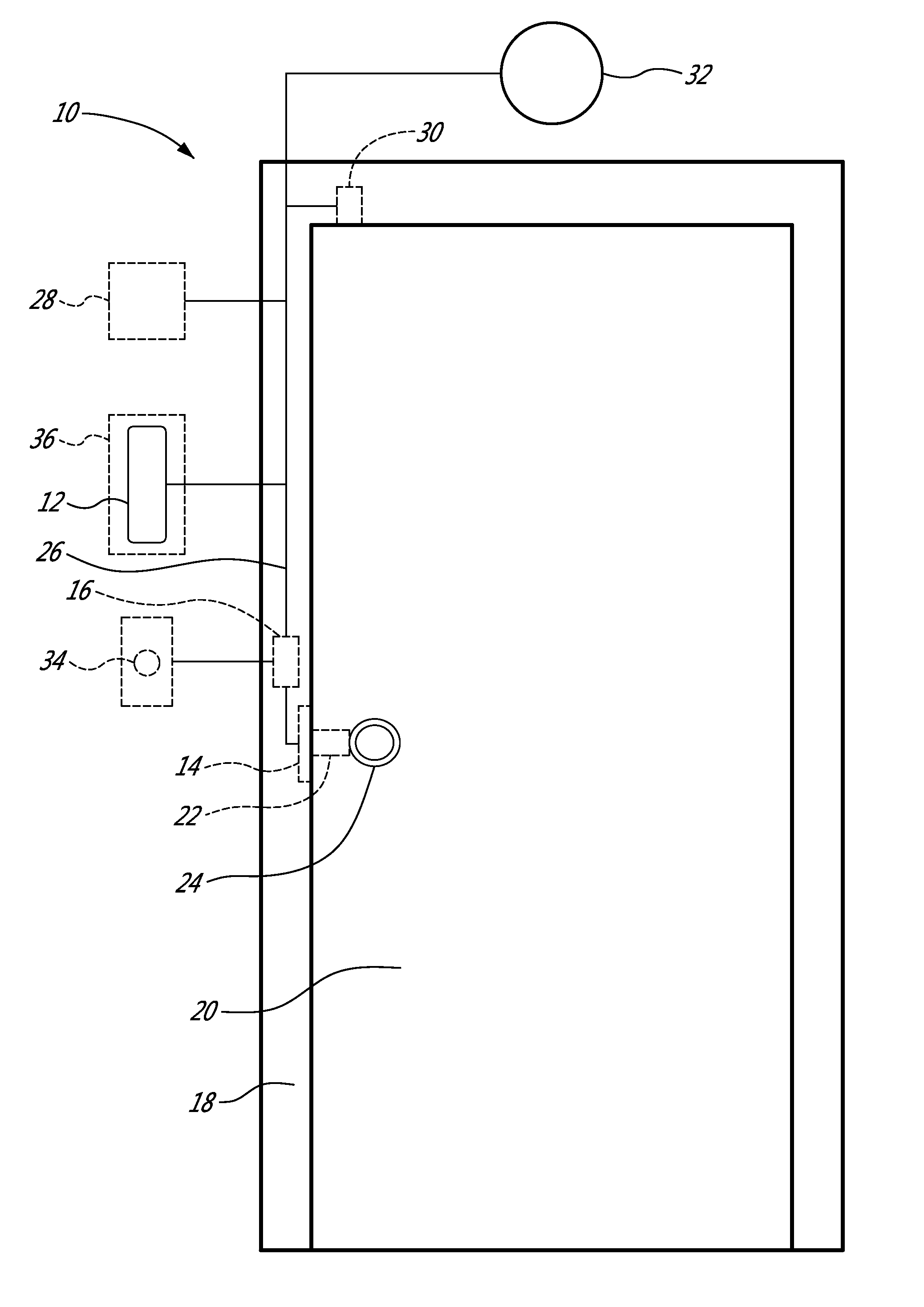
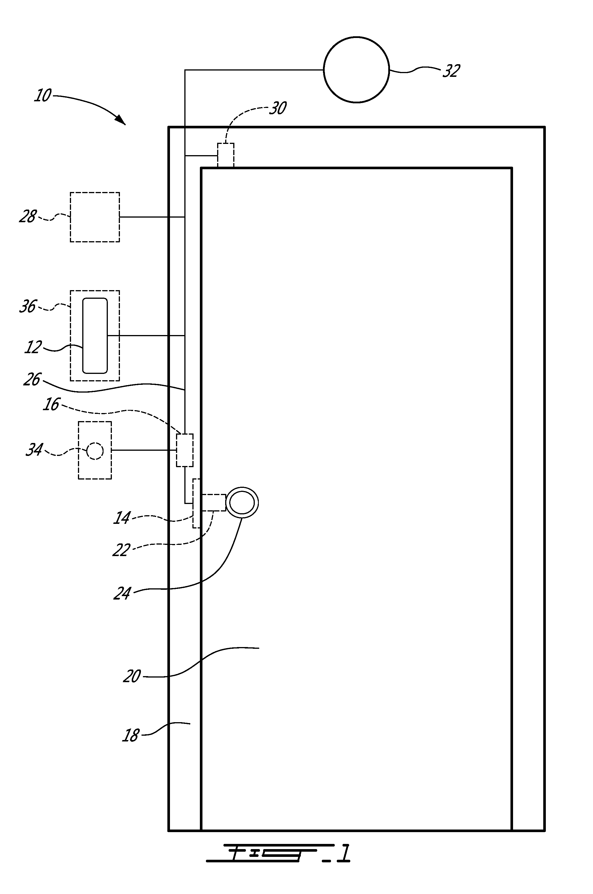
[0021]Referring now to FIG. 1, an electronic door access control system, generally referred to using the reference numeral 10, will now be described. The door access control system 10 comprises a key reader 12 and latch release mechanism 14 interconnected by a Door Control Unit (DCU) 16. The system is illustratively for use on a standard doorway comprising a metal door frame 18, door 20 and bored cylindrical lock 22 comprising a handle 24, or mortise lock, or the like. The DCU 16 is separate from the key reader 12 and, as will be discussed in more detail below, installed embedded in the door frame 18. The DCU 16 is interconnected with the key reader 12 illustratively via a communication cable 26 and an encrypted communications protocol. In a first illustrative embodiment the system 10 comprises an external power source 28, such as a power supply connected to the mains (not shown). Alternatively, the key reader 12 or DCU 16 could comprise an Ethernet interface (for example for connec...


PUM


Abstract

An electronic door lock system comprising a door control unit, a key reader and an encrypted binding between the key reader and the door control unit. When tampering is detected the encrypted binding is terminated thereby preventing the door from being opened. There is also disclosed a method for retrofitting a door comprising a key reader with a door control unit. The door control unit, key reader and the latch release mechanism may also be powered by a key comprising a power supply, the key also supplying a coded sequence to the door control unit.

Description

CROSS REFERENCE TO RELATED APPLICATIONS[0001]This application claims benefit, under 35 U.S.C. §119(e), of U.S. provisional application Ser. No. 61 / 771,427 filed on Mar. 1, 2013 which is incorporated herein in its entirety by reference.FIELD OF THE INVENTION[0002]The present invention relates to an electronic door access control system. In particular, the present invention relates to a system comprising a door control unit (DCU) for restricting access via a selectively lockable door way.BACKGROUND TO THE INVENTION[0003]One drawback with prior art electronic door access systems is that many of the elements necessary to open the door are collocated with either the key reader, the door lock or the striker plate. This means that the prior art door locks are relatively easy to compromise. Another drawback shown in the art is that in order to operate, the door must be supplied with a source of power, which is typically by means of a collocated battery or power supply attached to the mains....

Claims


Application Information

Patent Timeline
IPC IPC(8): G07C9/00
CPCG07C9/00007G07C9/00174G07C9/00563G07C9/0069G07C2209/62E05B47/0047G07C9/20
Inventor PAQUIN, YVES
Owner PAQUIN YVES
Why Eureka
Try Eureka