
Systems and methods of performing vibro-acoustic analysis of a structure

a technology of vibro-acoustic analysis and systems, applied in the direction of machines/engines, liquid/fluent solid measurement, fluid pressure measurement, etc., can solve the problems of large resources, computational intensive solution of equations in traditional numerical methods, and inability to achieve the effect of fast convergen

Active Publication Date: 2012-11-06
ANSYS
View PDF8 Cites 10 Cited by
  • Summary
  • Abstract
  • Description
  • Claims
  • Application Information

AI Technical Summary

Benefits of technology

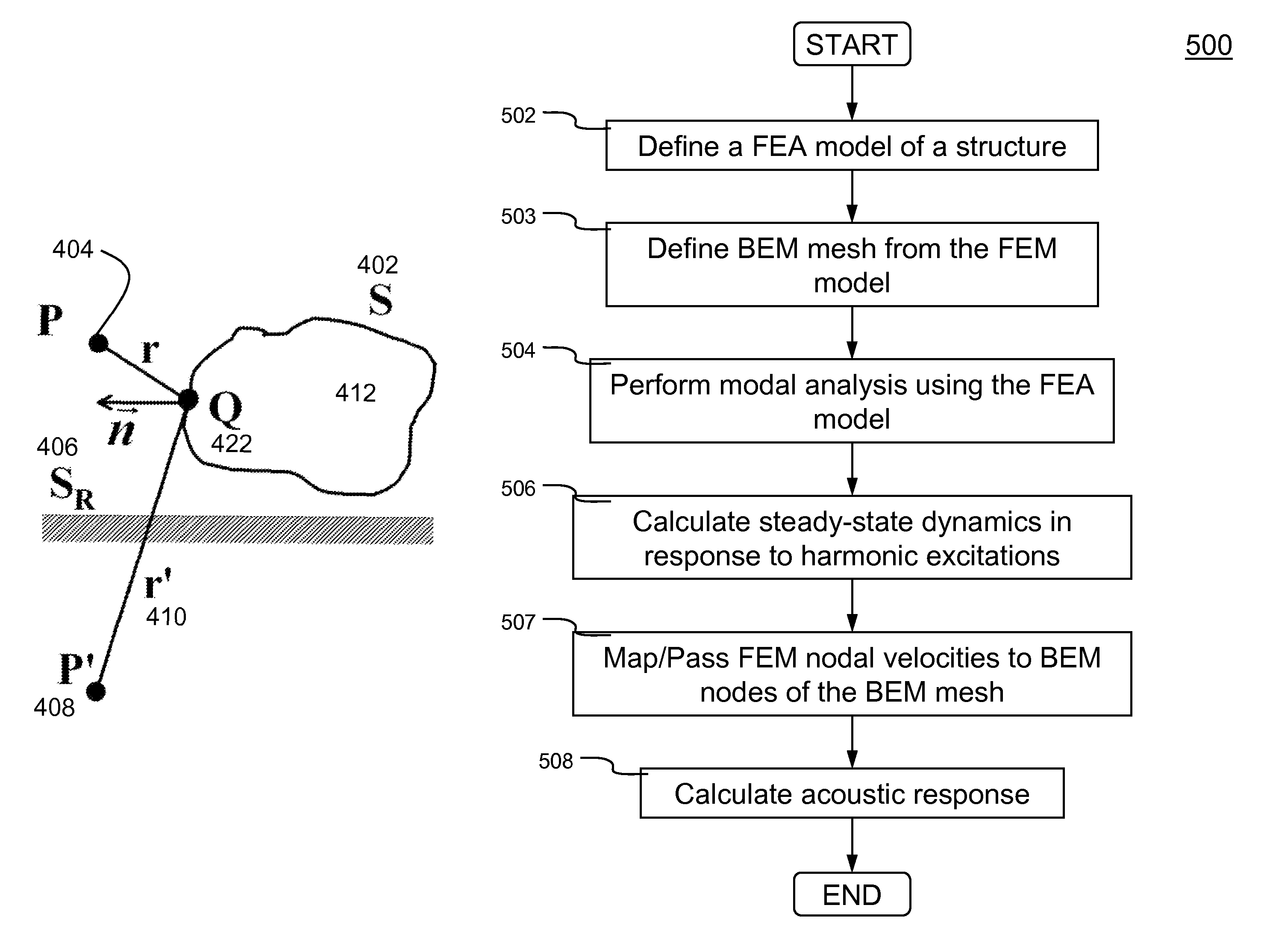
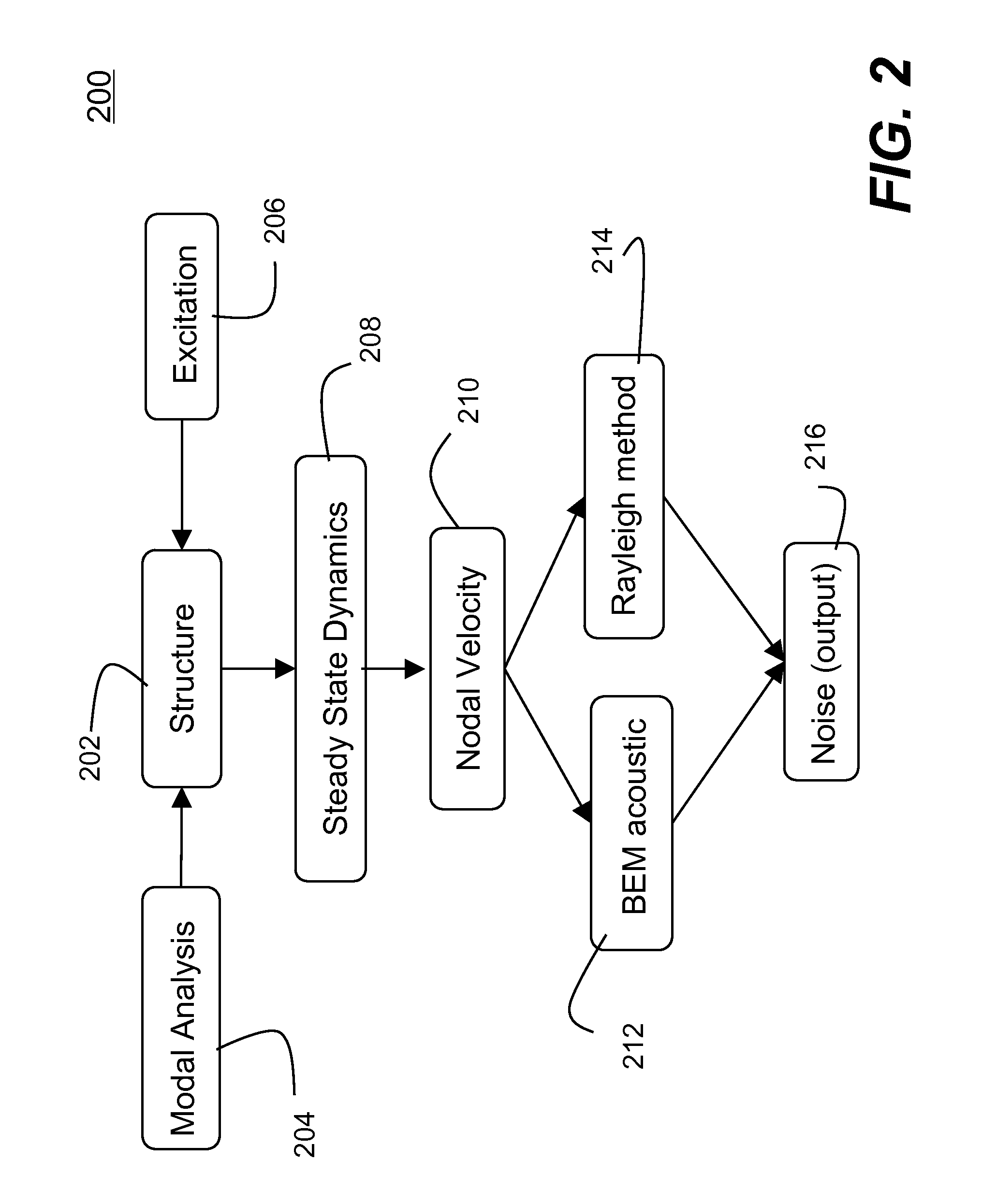
The present invention provides methods and systems for simulating acoustic fields in structures using vibro-acoustic analysis. The invention involves two stages: a steady state dynamic analysis and an acoustic analysis. The steady state dynamic analysis uses a finite element analysis model of the structure to obtain the results at desired locations in the structure, while the acoustic analysis uses the nodal velocities obtained from the dynamic analysis as a boundary condition. The invention also includes a modal analysis to extract natural vibration frequencies and vibration modes of the structure, followed by a finite element transient analysis for pre-stressed conditions. The resulting acoustics can be calculated using boundary element method or equivalent methods. The invention also utilizes parallel computing and low rank approximations for faster convergence. The technical effects of the invention include improved accuracy and efficiency in simulating acoustic fields in structures.

Problems solved by technology

One of the challenging FEA tasks is to simulate acoustic responses (e.g., noises) of a structure subjected to external excitations.
For systems with large number of FEA elements, solving these equations in traditional numerical methods becomes computational intensive and requires large resources.
These approaches not only require human intervention, but also are error prone.

Method used


Image

  • Systems and methods of performing vibro-acoustic analysis of a structure
  • Systems and methods of performing vibro-acoustic analysis of a structure
  • Systems and methods of performing vibro-acoustic analysis of a structure

Examples


Embodiment Construction

[0026]In the following description, numerous specific details are set forth in order to provide a thorough understanding of the present invention. However, it will become obvious to those skilled in the art that the present invention may be practiced without these specific details. The descriptions and representations herein are the common means used by those experienced or skilled in the art to most effectively convey the substance of their work to others skilled in the art. In other instances, well-known methods, procedures, components, and circuitry have not been described in detail to avoid unnecessarily obscuring aspects of the present invention.

[0027]Reference herein to “one embodiment” or “an embodiment” means that a particular feature, structure, or characteristic described in connection with the embodiment can be included in at least one embodiment of the invention. The appearances of the phrase “in one embodiment” in various places in the specification are not necessarily ...


PUM


Abstract

Methods and systems for simulating acoustic field resulted from particular excitations by performing vibro-acoustic analysis of a structure are disclosed. According to one aspect of the present invention, vibro-acoustic analysis of a structure is performed in two stages. First, steady state dynamic (SSD) responses are obtained using a finite element analysis model of a structure subject to harmonic excitations (e.g., external nodal loads, pressures, or enforced motions (e.g., ground motions), etc.). The steady state responses are the results (e.g., nodal velocities at desired locations of the structure) obtained in a finite element analysis in frequency-domain. Second, an acoustic analysis is conducted according to Helmholtz equation using the nodal velocities obtained at desired locations on the structure as a boundary condition. The acoustic analysis can be performed in a number of procedures (e.g., boundary element method, Rayleigh approximation method, etc.).

Description

CROSS REFERENCE TO RELATED APPLICATIONS[0001]This application claims priority from U.S. Provisional Patent Application Ser. No. 61 / 351,516 for the same title, filed on Jun. 4, 2010, the entire content of which is incorporated herein by reference.BACKGROUND OF THE INVENTION[0002]1. Field of the Invention[0003]The present invention generally relates to computer-aided engineering analysis of a structure, more particularly to systems and methods of performing vibro-acoustic analysis of a structure subjected to harmonic excitations (i.e., loads).[0004]2. Description of the Related Art[0005]The finite element method (FEM) (sometimes referred to as finite element analysis (FEA)) is a numerical technique for finding approximate solutions of partial differential equations (PDE) as well as of integral equations. The solution approach is based either on eliminating the differential equation completely (steady state problems), or rendering the PDE into an approximating system of ordinary differ...

Claims


Application Information

Patent Timeline
Patent Type & Authority Patents(United States)
IPC IPC(8): G06F17/50
CPCG06F17/5018G06F30/23
Inventor HUANG, YUNSOULI, MHAMEDASHCRAFT, C. CLEVELAND
Owner ANSYS
Learn More