
Low pressure carbonitriding method and device

a carbonitriding and low-pressure technology, applied in the direction of liquid surface applicators, coatings, metallic material coating processes, etc., can solve the problems of difficult industrial use of such a method, excessive processing time, and the effect of nitriding step after carburizing

Active Publication Date: 2012-11-06
ECM TECHNOLOGY PTY LTD
View PDF13 Cites 14 Cited by
  • Summary
  • Abstract
  • Description
  • Claims
  • Application Information

AI Technical Summary

Benefits of technology

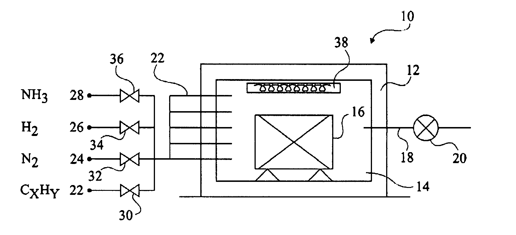
"The present invention provides a method for low-pressure carbonitriding of steel parts that allows for accurate and reproducible carbon and nitrogen concentration profiles. The method is compatible with industrial processing and the furnace used for carbonitriding is simple in design. The method involves an alternation of first and second steps, with carburizing gas being injected during the first steps and nitriding gas being injected during at least part of at least two second steps. The method can be carried out at a constant pressure lower than 1,500 pascals and at a temperature level between 800°C and 1050°C. The invention also provides a carbonitriding furnace that can maintain a reduced internal pressure and a temperature level for the part being processed."

Problems solved by technology

A disadvantage of the first carbonitriding method example described in US publication 2004 / 0187966 is that the nitriding step is performed after the carburizing step, at a temperature level lower than the carburizing temperature level.
The total processing time may thus be excessively long, which makes the use of such a method in an industrial context difficult.
A disadvantage of the second carbonitriding method example described in US publication 2004 / 0187966 is due to the fact that the carburizing and nitriding gases are injected simultaneous into the furnace enclosure.
It is then difficult to accurately control the gaseous environment in the enclosure and, accordingly, to accurately and reproducibly control the nitrogen and carbon concentration profiles obtained in the processed parts.

Method used


Image

  • Low pressure carbonitriding method and device
  • Low pressure carbonitriding method and device
  • Low pressure carbonitriding method and device

Examples


Embodiment Construction

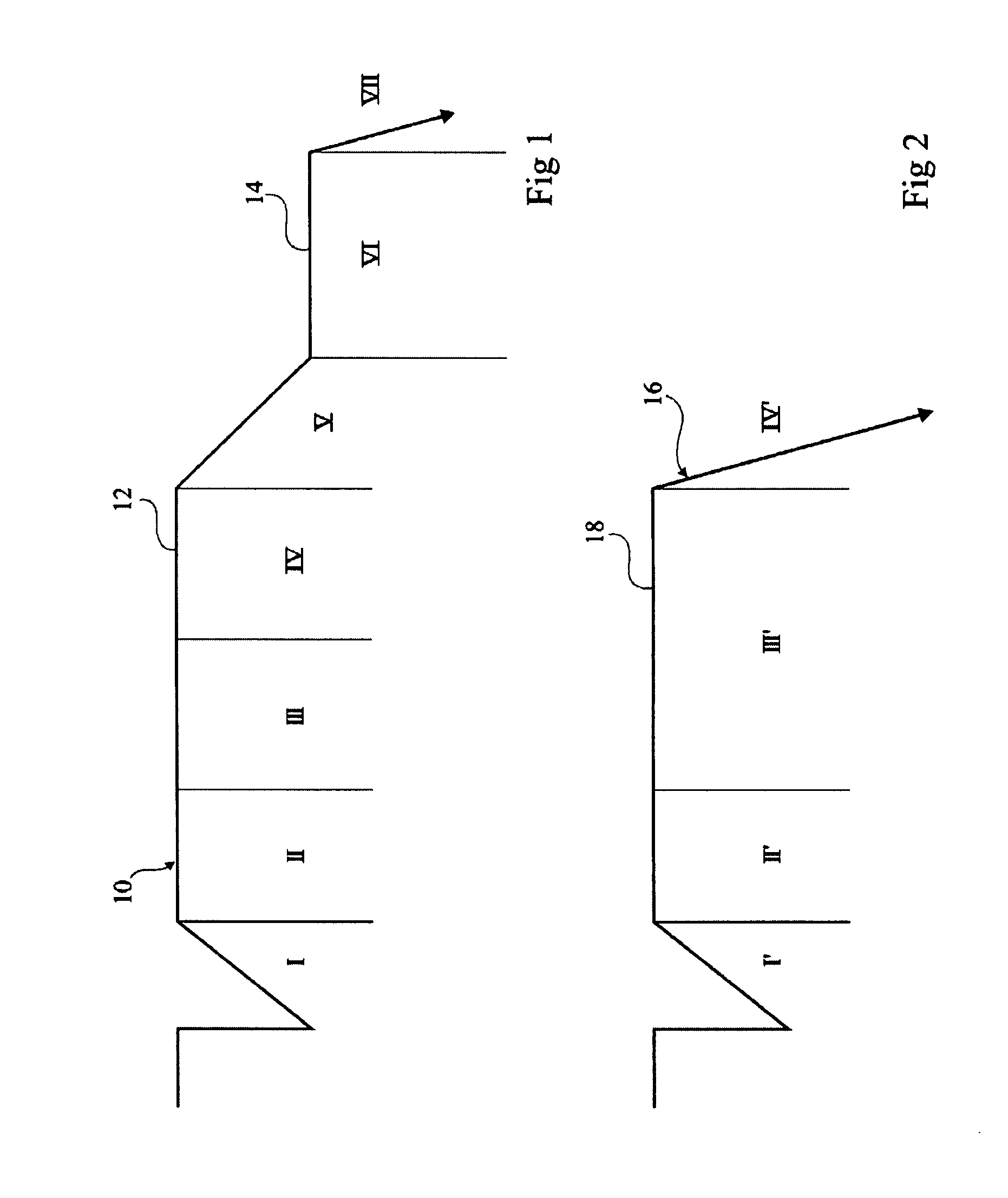
[0031]The present invention comprises carrying out in an enclosure containing steel parts to be processed maintained at a substantially constant temperature, an alternation of carbon enrichment steps during which a carburizing gas is injected into the enclosure under a reduced pressure and of carbon diffusion steps during which the carburizing gas injection is interrupted. The present invention comprises providing the injection, into the enclosure, of a nitriding gas for all or part of the carbon diffusion steps. The carbon enrichment steps then correspond to nitrogen diffusion steps. The nitriding gas is injected during at least part of at least two carbon diffusion steps, that is, during at least part of a carbon diffusion step interposed between two carbon enrichment steps. This advantageously enables accurately and reproducibly controlling the carbon and nitrogen concentration profiles obtained in the processed parts, since the nitriding gas injection is performed separately fro...


PUM

PropertyMeasurementUnit
pressureaaaaaaaaaa
temperatureaaaaaaaaaa

Abstract

A method for carbonitriding a steel part arranged in an enclosure maintained at a reduced internal pressure, the part being maintained at a temperature level, comprising an alternation of first and second steps, a carburizing gas being injected into the enclosure during the first steps only and a nitriding gas being injected into the enclosure only during at least part of at least two second steps.

Description

[0001]This application is a national stage application under 35 U.S.C. §371 of International Application No. PCT / FR2006 / 050357 and claims the benefit of French Application No. 05 / 50996, filed Apr. 19, 2005, the entire disclosures of which are incorporated herein by reference.FIELD OF THE INVENTION[0002]The present invention relates to methods for processing steel parts, and more specifically carbonitriding methods, that is, methods for introducing carbon and nitrogen at the surface of steel parts to improve their hardness and their fatigue behavior.DISCUSSION OF PRIOR ART[0003]There exist several types of methods for carbonitriding steel parts enabling introduction of carbon and nitrogen at the surface of parts, down to depths that can reach several hundreds of micrometers.[0004]A first category of carbonitriding methods corresponds to so-called high-pressure carbonitriding methods since the enclosure containing the parts to be processed is maintained at a pressure generally close t...

Claims


Application Information

Patent Timeline
Patent Type & Authority Patents(United States)
IPC IPC(8): C23C8/34
CPCC23C8/34C23C8/32C23C8/30
Inventor BERLIER, JEANGOLDSTEINAS, AYMERICDOUSSOT, XAVIER
Owner ECM TECHNOLOGY PTY LTD
Learn More