
Conductor-connecting washer, connection mechanism using the same, and method of manufacturing conductor-connecting washer

a technology of conductors and washers, applied in the direction of cell components, coupling device connections, contact members penetrating/cutting insulation/cable strands, etc., can solve the problems of inability to detachment after joining, inability to increase strength, and difficulty in achieving a sufficiently low contact resistance in a flat surface connection, etc., to achieve the effect of reducing the number of contact protrusions, and achieving the effect of reducing

Inactive Publication Date: 2012-11-06
JAPAN AVIATION ELECTRONICS IND LTD
View PDF17 Cites 41 Cited by
  • Summary
  • Abstract
  • Description
  • Claims
  • Application Information

AI Technical Summary

Benefits of technology

The solution enables reliable electrical connections with lower contact resistance and reduced manufacturing complexity, allowing for efficient current flow and stable connections with smaller loads, suitable for high-current applications.

Problems solved by technology

However, it is difficult to achieve a sufficiently low contact resistance in a connection between flat surfaces with merely a spring force of a leaf spring.
However, this does not increase strength after joining.
Also, detachment cannot be made after joining.
However, Patent literature 3 does not describe the shape or arrangement of the protrusion in detail.
Also, the disclosed conductive member can only be manufactured through cutting work or forging.
Cutting work is likely to increase processing cost and is considered difficult for practical application.
In the case of manufacturing by forging, the processing cost also increases, although to a lesser extent than the cutting work.
Also, in the case of manufacturing by forging, it is difficult to make a protrusion with a sharp tip.
Thus, it is difficult to remove an oxide with the protrusion, whereby application of considerable load is presumably necessary.
However, since the contortion angle of the teeth is small, entering inside a terminal or a bus bar is not feasible even through insertion between the terminal and the bus bar.
Thus, a favorable electrical connection with small load is difficult.

Method used


Image

  • Conductor-connecting washer, connection mechanism using the same, and method of manufacturing conductor-connecting washer
  • Conductor-connecting washer, connection mechanism using the same, and method of manufacturing conductor-connecting washer
  • Conductor-connecting washer, connection mechanism using the same, and method of manufacturing conductor-connecting washer

Examples


first embodiment

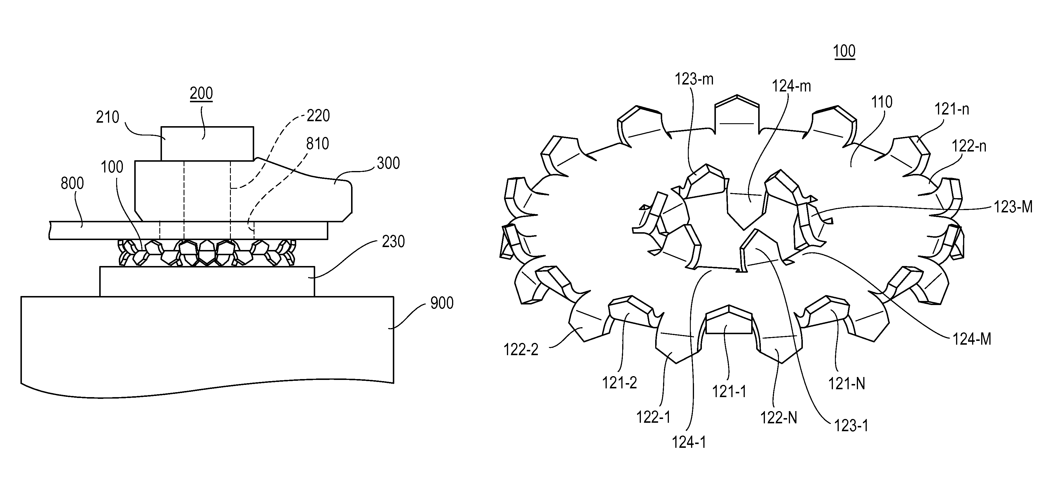
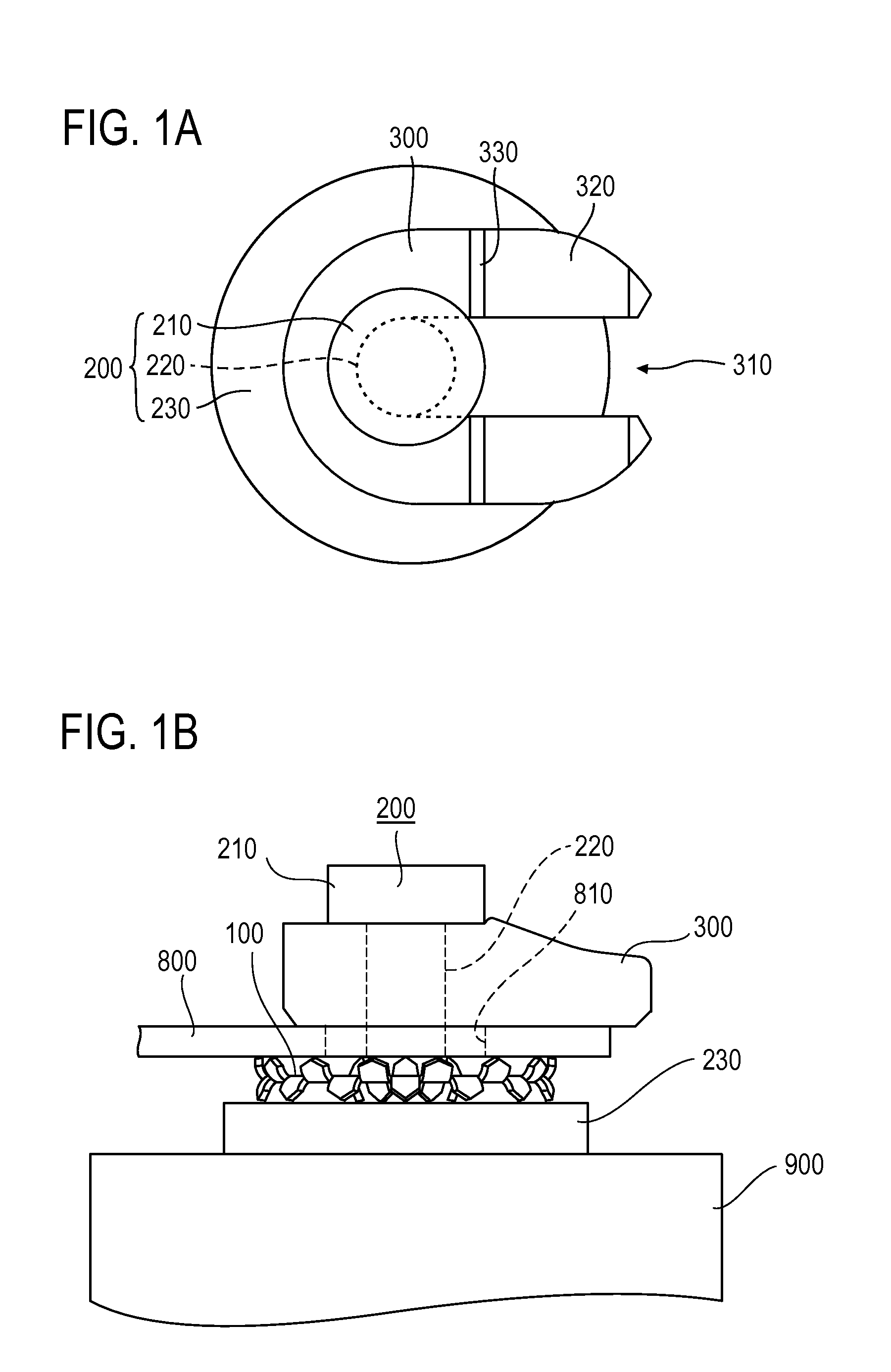
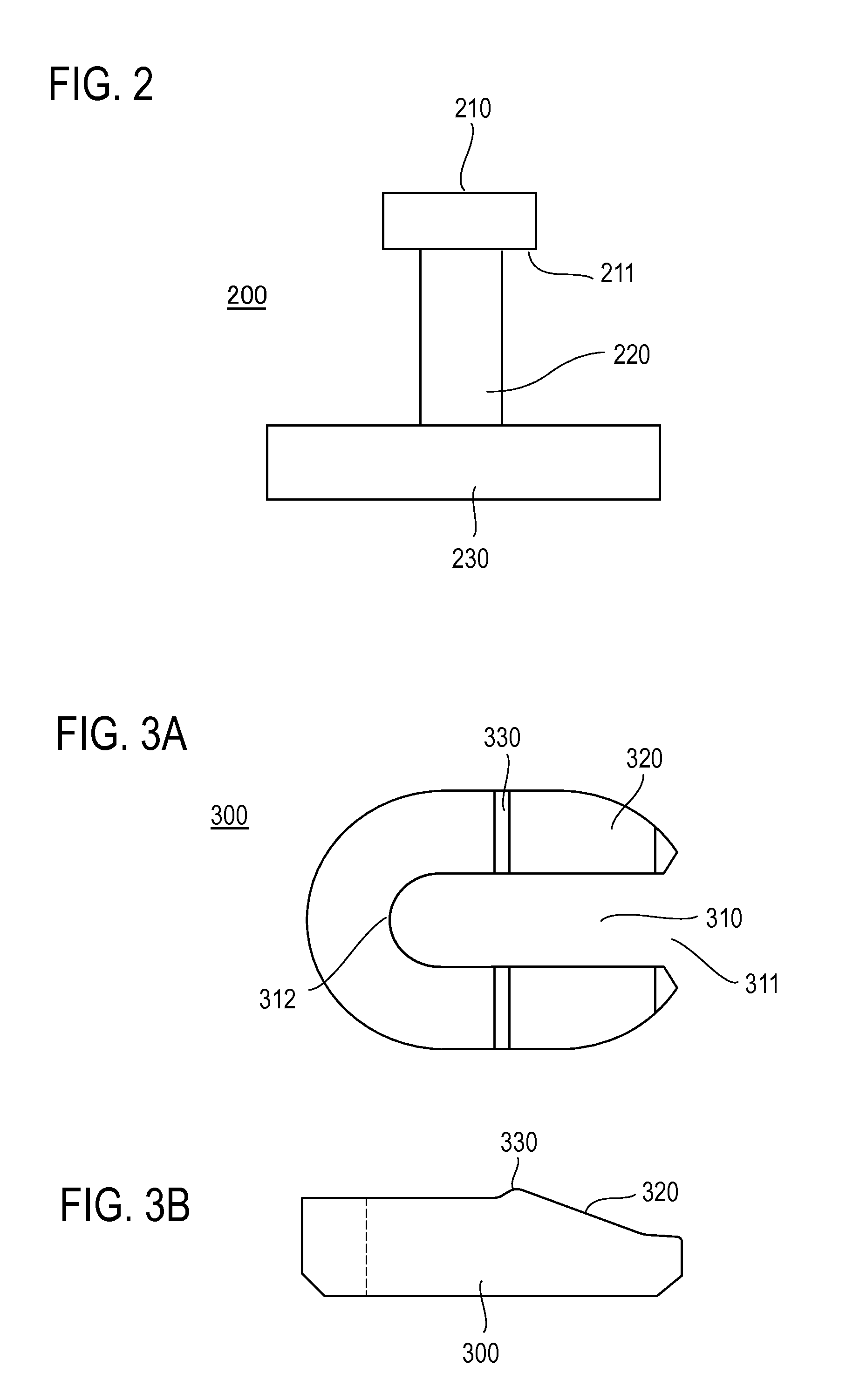
[0045]FIG. 1A is a plan view showing a terminal 200 used for a connection mechanism of the present invention and a cam block 300 attached to the terminal 200. FIG. 1B is a side view showing a configuration of the connection mechanism. The connection mechanism is a mechanism which connects the terminal 200 attached to an electrical part 900 and a bus bar 800 having a bus bar hole 810. The terminal 200 secured to the electrical part 900 by soldering or welding or integrally formed as a part of the electrical part includes, as shown in a side view in FIG. 2, a disc-shaped terminal base portion 230, a cylinder-shaped shaft 220 which is integrally formed perpendicularly in the middle of the terminal base portion 230, and a circular terminal head 210 which is integrally formed at the front end of the shaft 220 and larger than the diameter of the shaft 220. A conductor-connecting washer 100, the bus bar 800, and the cam block 300 are arranged in order in the direction from the terminal bas...


PUM

PropertyMeasurementUnit
angleaaaaaaaaaa
angleaaaaaaaaaa
voltageaaaaaaaaaa

Abstract

A conductor-connecting washer arranged between two conductors to electrically connect the two conductors includes a metal plate portion including a washer hole in the middle and 24 or more contact protrusions integrally formed on each of both surfaces of the plate portion, 16 or more of which are bent alternately toward each of both surface sides along the outer circumference of the plate portion and 8 or more of which are bent alternately toward each of both surface sides along the inner circumference of the washer hole.

Description

TECHNICAL FIELD[0001]The present invention relates to a conductor-connecting washer and a connection mechanism using the same for electrically connecting two conductors and a method of manufacturing a conductor-connecting washer.BACKGROUND ART[0002]A bus bar is often used for electrically connecting terminals of electrical parts such as a bipolar battery. A terminal of an electrical part and a bus bar is mainly connected by ultrasonic welding or thread-tightening. Conventional art relating to such connection of electrical parts or connection of a terminal of an electrical part and a bus bar is disclosed in Japanese Patent Application Laid Open No. 2008-140624 (hereinafter referred to as Patent literature 1), Japanese Patent Application Laid Open No. 2005-327677 (hereinafter referred to as Patent literature 2), and Japanese Patent Application Laid Open No. 2005-268029 (hereinafter referred to as Patent literature 3). Also, research on contact of two conductors has been conducted for ...

Claims


Application Information

Patent Timeline
Patent Type & Authority Patents(United States)
IPC IPC(8): H01R11/11H01M50/503H01M50/516H01M50/522
CPCH01R4/26H01M2/202Y02E60/10H01R4/48H01M50/522H01M50/516H01M50/503H01M50/183H01M50/50H01M50/543
Inventor KUWAHARA, TAKASHIISHIYAMA, YOSHIAKI
Owner JAPAN AVIATION ELECTRONICS IND LTD
Learn More