
Method of creating a honeycomb core using a serpentine welding path

a technology of honeycomb cores and serpentine welding paths, which is applied in the field of honeycomb cores, can solve the problems of uneven welding surface, foil curling on the side of the weld path, and small shrinkage, and achieve the effect of reducing the curvature of a stack of welded parts

Active Publication Date: 2012-11-06
DECEASED ESTATE OF JEFFREY DON JOHNSON +1
View PDF8 Cites 0 Cited by
  • Summary
  • Abstract
  • Description
  • Claims
  • Application Information

AI Technical Summary

Benefits of technology

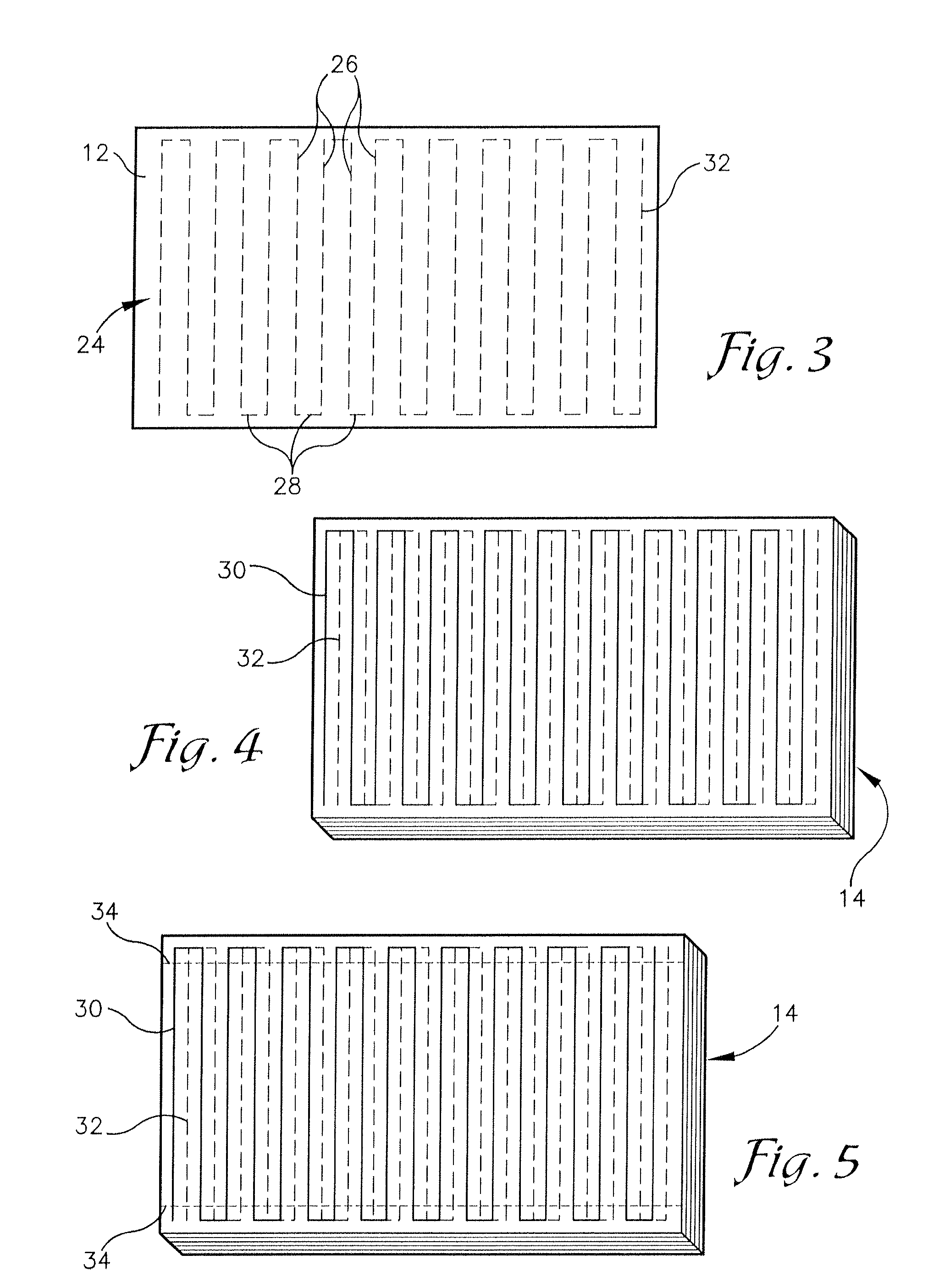
[0008]Embodiments of the present invention solve the above-mentioned problems and provide a distinct advance in the art of manufacturing honeycomb cores. More particularly, embodiments of the invention provide a method of creating a honeycomb core that includes the use of a serpentine welding pattern to reduce the curvature of a stack of welded metal sheets.
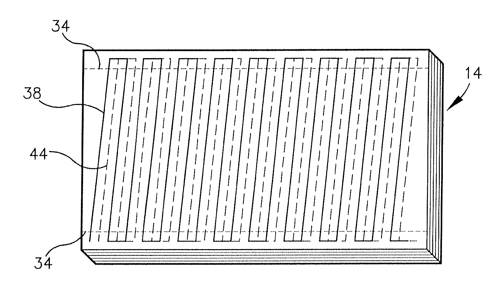
[0011]Other embodiments of the current invention include a method for creating an angled honeycomb core that utilizes a serpentine welding pattern which avoids having to trim a stack of sheets that forms the core along the larger dimension of the stack. At least a portion of the steps of the method may include placing a first metal sheet on top of a second metal sheet to create a stack and welding the first metal sheet to the second metal sheet using a first angled serpentine welding pattern that includes a plurality of long welds and a plurality of short welds, wherein the angle between the long welds and the short welds is a first angle between ninety degrees and zero degrees. The method further includes welding a third metal sheet to the top of the stack using a second angled serpentine welding pattern that includes a plurality of long welds and a plurality of short welds, wherein the angle between the long welds and the short welds is the first angle and such that the long welds of the second angled serpentine welding pattern are shifted from the long welds of the first angled serpentine welding pattern and a portion of each short weld of the second angled serpentine welding pattern overlaps a portion of each short weld of the first angled serpentine welding pattern.

Problems solved by technology

Each weld path may cause a slight shrinkage in the foil along the weld path, which in turn may cause the foil to curl on the sides of the weld path.
The curling may lead to an uneven welding surface and curvature of the stack of sheets near the edges.
Since the integrity of the weld and the quality of the core may depend on the flatness of the welding surface, either the size of the core may be limited or flattening techniques may need to be applied.
Correcting the curvature of the stack adds time and expense to the production of the honeycomb core.
Since the sides of the stack that form the faces are usually along the largest dimension of each sheet, cutting and removing the stack along the face sides wastes a large amount of core material.

Method used


Image

  • Method of creating a honeycomb core using a serpentine welding path
  • Method of creating a honeycomb core using a serpentine welding path
  • Method of creating a honeycomb core using a serpentine welding path

Examples


Embodiment Construction

[0032]The following detailed description of the invention references the accompanying drawings that illustrate specific embodiments in which the invention can be practiced. The embodiments are intended to describe aspects of the invention in sufficient detail to enable those skilled in the art to practice the invention. Other embodiments can be utilized and changes can be made without departing from the scope of the present invention. The following detailed description is, therefore, not to be taken in a limiting sense. The scope of the present invention is defined only by the appended claims, along with the full scope of equivalents to which such claims are entitled.

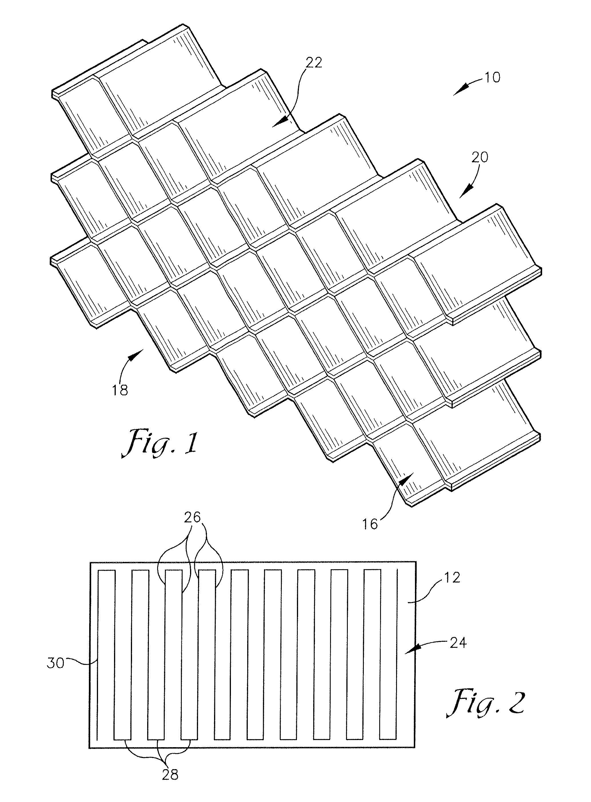
[0033]A honeycomb core 10, manufactured utilizing a method in accordance with various embodiments of the current invention, is shown in FIG. 1. The core 10 may be formed from a plurality of sheets 12 that are bonded together in a stack 14 and then expanded. Once expanded, as shown in FIG. 1, the core 10 may include a pl...


PUM

PropertyMeasurementUnit
angleaaaaaaaaaa
angleaaaaaaaaaa
angleaaaaaaaaaa

Abstract

A honeycomb core is created from a stack of metal sheets that are welded together using a serpentine weld path. Each sheet in the stack is welded to the sheet underneath. All the odd-numbered sheets, excluding the bottom sheet, are welded using a first serpentine welding pattern that includes a plurality of long welds and a plurality of short welds. All the even-numbered sheets are welded using a second serpentine welding pattern that includes a plurality of long welds and a plurality of short welds, such that the long welds of the second serpentine welding pattern are shifted from the long welds of the first serpentine welding pattern. When a sufficient number of sheets have been welded, the stack is trimmed to remove the short welds. The stack is expanded by pulling the sheets one from another to form the honeycomb core.

Description

BACKGROUND OF THE INVENTION[0001]1. Field of the Invention[0002]Embodiments of the present invention relate to honeycomb cores. More particularly, embodiments of the present invention relate to methods for creating honeycomb cores by welding a plurality of metal sheets together using a serpentine welding path.[0003]2. Description of the Related Art[0004]A honeycomb core is a structure formed from a plurality of cells that are joined together, wherein each cell may be open-ended with a plurality of walls that surround empty space. The honeycomb core is typically sandwiched between other materials to generally provide lightweight support strength over an area. Honeycomb cores may also be used for acoustic damping, energy absorption, and airflow direction. Honeycomb cores may be utilized in the aerospace, aircraft, automotive, marine, and railcar industries, among others.[0005]One approach to creating honeycomb cores is to create a stack of sheets, where each sheet is bonded to the she...

Claims


Application Information

Patent Timeline
Patent Type & Authority Patents(United States)
IPC IPC(8): B23K31/02
CPCB23K26/246B23K2201/02B23K2201/14B23K26/244B23K2101/02B23K2101/14
Inventor JOHNSON, JEFFREY D.
Owner DECEASED ESTATE OF JEFFREY DON JOHNSON
Learn More