Eureka AIR delivers breakthrough ideas for toughest innovation challenges, trusted by R&D personnel around the world.

System and method for digital interference cancellation

a technology of digital interference and cancellation method, applied in the direction of transmission, electrical equipment, etc., can solve the problems of inability to achieve the effect of other methods, inability to easily achieve interferer synthesis features that cannot be easily achieved by other methods, and inability to achieve broadband nonlinear distortion, etc., to achieve the effect of improving the effective dynamic range of an adc, facilitating the receiver design, and efficient implementation

Active Publication Date: 2012-10-30
HYPRES
View PDF4 Cites 26 Cited by
  • Summary
  • Abstract
  • Description
  • Claims
  • Application Information

AI Technical Summary

Benefits of technology

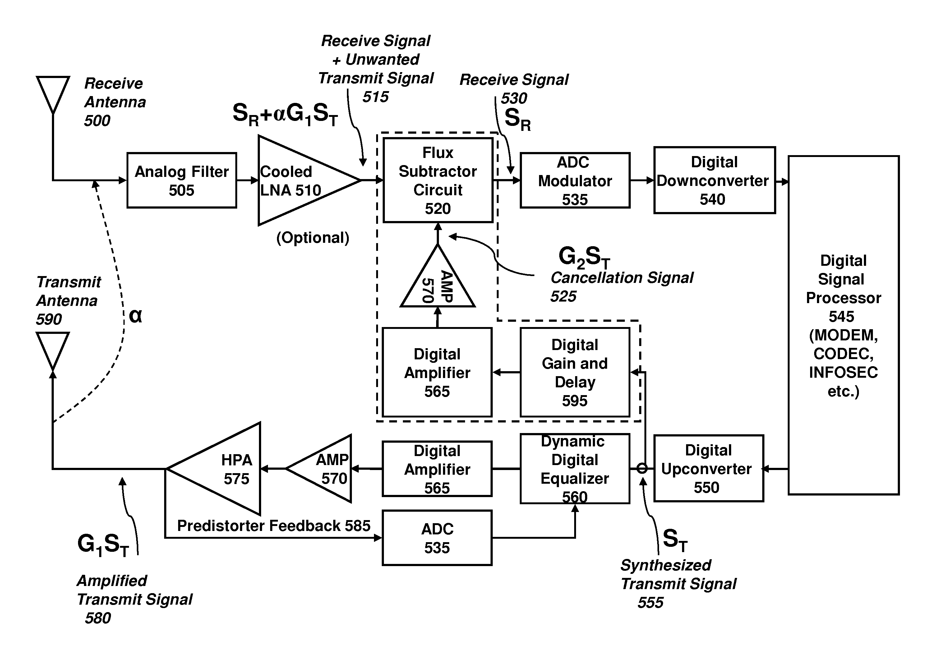
[0012]According to a preferred system architecture of the present technology, a Digital-RF™ interference cancellation signal, i.e., a digital bitstream which is oversampled with respect to a corresponding analog radio frequency waveform, may be directly synthesized in a process without analog upconversion (and may even be combined digitally), followed by conversion to the analog representation in a digital-to-analog converter (DAC) and analog subtraction from the input signal received from the antenna, before the ADC of the receiver (see FIG. 4). This requires similar ultrafast sampling technology that is used in the Digital-RF™ receiver, and therefore can be implemented efficiently. Indeed, the use of predictive peak amplitude reduction, from interferers or even the normal expected signal to be received, can facilitate the receiver design, since the technology will increase the effective dynamic range of an ADC.
[0013]It is noted that, in radio frequency electronics, especially dealing with broadcast signals over 1 GHz, the modulation of symbols is typically much less than 1 symbol / MHz of raw spectrum; that is, the modulation state of a signal will extend over multiple peaks and valleys of the radio frequency carrier. Therefore, an interference reduction system which responds in near real time to interference or saturation conditions of the ADC may be able to successfully demodulate a symbol in the radio frequency transmission, even if the ADC is initially saturated by the received signal. Even if the interference or saturation cancellation system does not respond within the minimum symbol timing, typically an interference condition is quasi-static and extends over multiple symbol periods. Therefore, error detection and correction codes provided within a digital communication may permit tolerance to some degree of time lag in establishing the interference or saturation cancellation conditions and / or agile interference conditions. It is noted that, in the case of a saturating signal, as compared to an interferer, the system may be configured to provide a controllable attenuation of the signal, rather than a successive-approximation or half-flash type signal amplitude reduction.
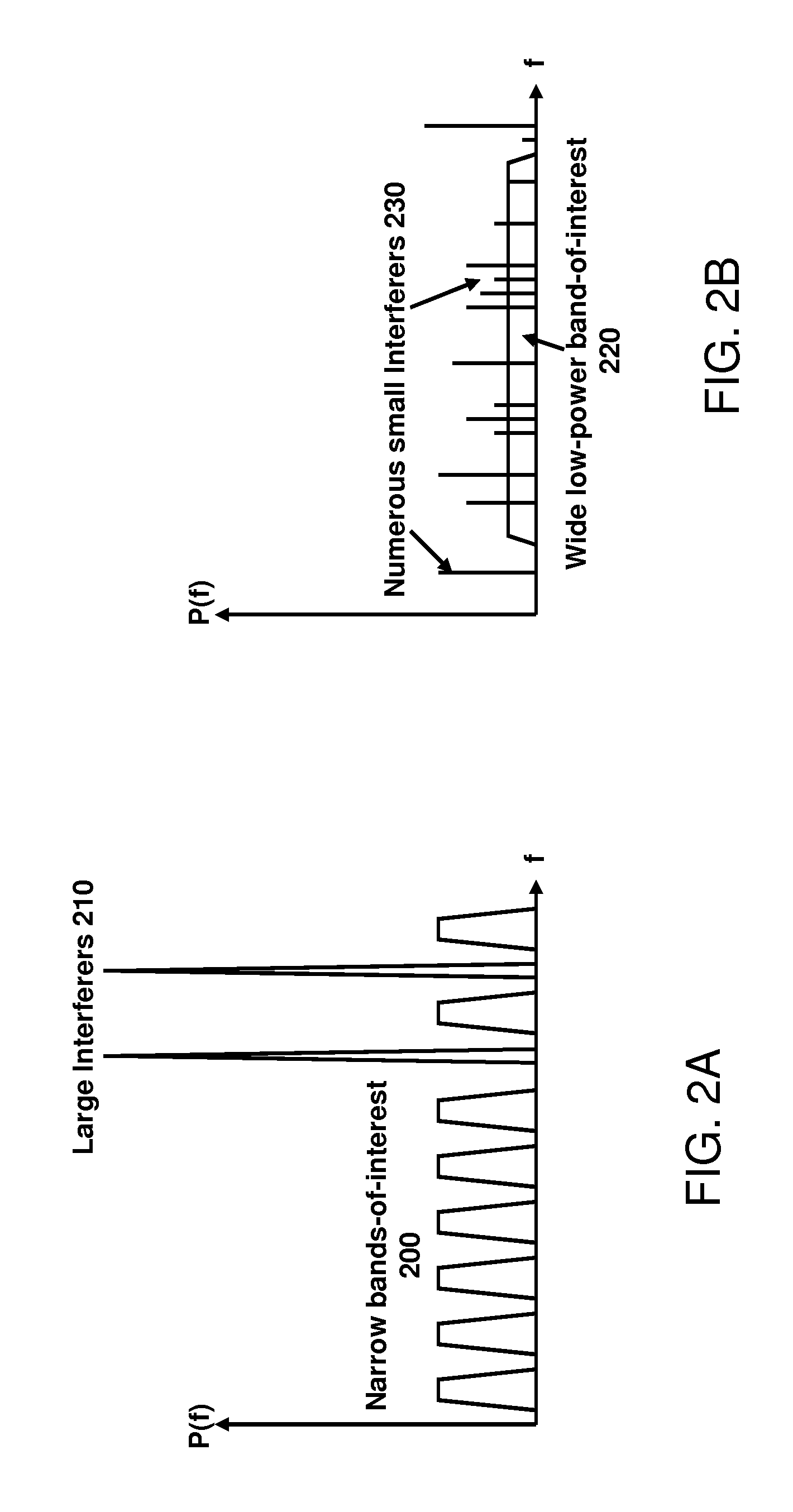
[0017]Typically, a radio receiver has limited complexity, and cannot analyze each peak within a band to determine whether it is part of a desired communication or represents interference (i.e., a spur). Therefore, it is desired to reduce the absolute amplitude of such spurs and this increase the spur-free dynamic range (SDFR). Thus, in accordance with one aspect of the technology, a feedback controlled signal is injected into an analog radio frequency signal which reduces an amplitude of a large amplitude interfering signal, and thus also reduces the amplitude of intermodulation spurs associated with that interfering signal. It is noted that the spurs are considered a form of noise, and therefore a reduction in the relative amplitude of the spurs as compared to the signal of interest increases a signal to noise ratio (SNR) or a signal to noise and distortion (SINAD) ratio.
[0020]The present technology addresses, for example, the critical co-site interference problem with an improved architecture that permits wideband cancellation of undesired high power signals, thereby providing better utilization of the available dynamic range. A preferred embodiment of the architecture employs a flux subtractor preceding the ADC modulator, which performs accurate subtraction of unwanted signals before the front-end of a receiver, and thus enhances its operation in a high electromagnetic interference (EMI) environment. Such a flux subtractor is compatible with superconducting RSFQ circuitry, and is thus readily integrated. Likewise, the flux subtractor produces low distortion, thus avoiding substantial tradeoffs. Of course, other architectures may be employed to selectively subtract an interferer from a received signal, such as a current summer. The flux subtractor architecture potentially allows a plurality of signals to be coupled concurrently, and thus permits a parallelization of interference signal processing, as may be desired or required.
[0037]The apparatus may further comprise an element through which the modified analog radio frequency signal is processed, having an associated non-linear distortion, wherein the cancellation signal improves a signal to noise and distortion ratio of the processed modified analog radio frequency signal.

Problems solved by technology

This Digital-RF™ interferer synthesis has several features that cannot be easily achieved by other methods.
Further, broadband nonlinear distortion can be generated, which might simulate the distortion of a high-power transmitter that is causing the interference.
For a Digital-RF™ transceiver with incoming and outgoing signals in nearby bands, co-site interference can be a serious problem.

Method used


Image

  • System and method for digital interference cancellation
  • System and method for digital interference cancellation
  • System and method for digital interference cancellation

Examples


Embodiment Construction

[0048]A typically encountered problem is presented in FIG. 1. A radio communication system comprises both a receiver and a transmitter (FIG. 1), which are typically located near each other (co-located or co-site), The radio receiver antenna 100 receives not only the desired signal, but also undesired interfering signals broadcast from one or more nearby transmit antennas 160, and potentially even deliberate jamming signals 170. The receiver is, of course, designed to detect weak signals, with a low-noise amplifier LNA 110 and a sensitive receiver chain 120, finally ending with baseband signals that may be converted to digital form and processed by a digital signal processor 130. In contrast, the transmitter chain 140 generates large signals which are amplified in a high-power amplifier HPA 150. Even a small fraction of the large transmit signal can saturate elements within the receiver. The receiver, including but not limited to the LNA 110, has an amount of nonlinearity which may g...


PUM


Abstract

A system and method for receiving a signal, comprising an input adapted to receive a radio frequency signal having a strong interferer; a signal generator, adapted to produce a representation of the interferer as an analog signal generated based on an oversampled digital representation thereof; and a component adapted to cancel the strong interferer from radio frequency signal based on the generated analog signal to produce a modified radio frequency signal substantially absent the interferer. The system typically has a nonlinear component that either saturates or produces distortion from the strong interferer, which is thereby reduced. The system preferably employs high speed circuits which digitize and process radio frequency signals without analog mixers.

Description

RELATED APPLICATIONS[0001]The present application is a continuation of U.S. patent application Ser. No. 12 / 434,590, filed May 1, 2009 now U.S. Pat. No. 8,055,235, which is a non-provisional of U.S. Provisional Application 61 / 050,161, filed May 2, 2008, the entirety of which is expressly incorporated herein by reference.BACKGROUND OF THE INVENTION[0002]1. Field of the Invention[0003]The present invention relates to interference cancellation techniques, and more particularly, to digital interference techniques at radio frequencies.[0004]2. Description of the Prior Art[0005]The problem of interference in RF receivers is well known. One approach is to try to filter the interferers; the other is to actively cancel them by generating a signal corresponding to each interferer and subtracting it from the input. In the former technique, it is possible that signal components are lost in the filter, since these generally cannot distinguish between the interferer and the signal of interest if i...

Claims


Application Information

Patent Timeline
Patent Type & Authority Patents(United States)
IPC IPC(8): H04B1/10
CPCH04B1/525H04B1/10
Inventor GUPTA, DEEPNARAYANINAMDAR, AMOL
Owner HYPRES
Why Eureka
Eureka Blog
Learn More