Imaging device and image processing program for estimating fixed pattern noise from partial noise output of available pixel area
a technology of image processing and fixed pattern noise, which is applied in the field of image processing, can solve the problems of reducing the speed of continuous shooting, affecting the quality of image processing, so as to shorten the time required for a photographing sequence
- Summary
- Abstract
- Description
- Claims
- Application Information
AI Technical Summary
Benefits of technology
Problems solved by technology
Method used
Image
Examples
first embodiment
Configuration Description of First Embodiment
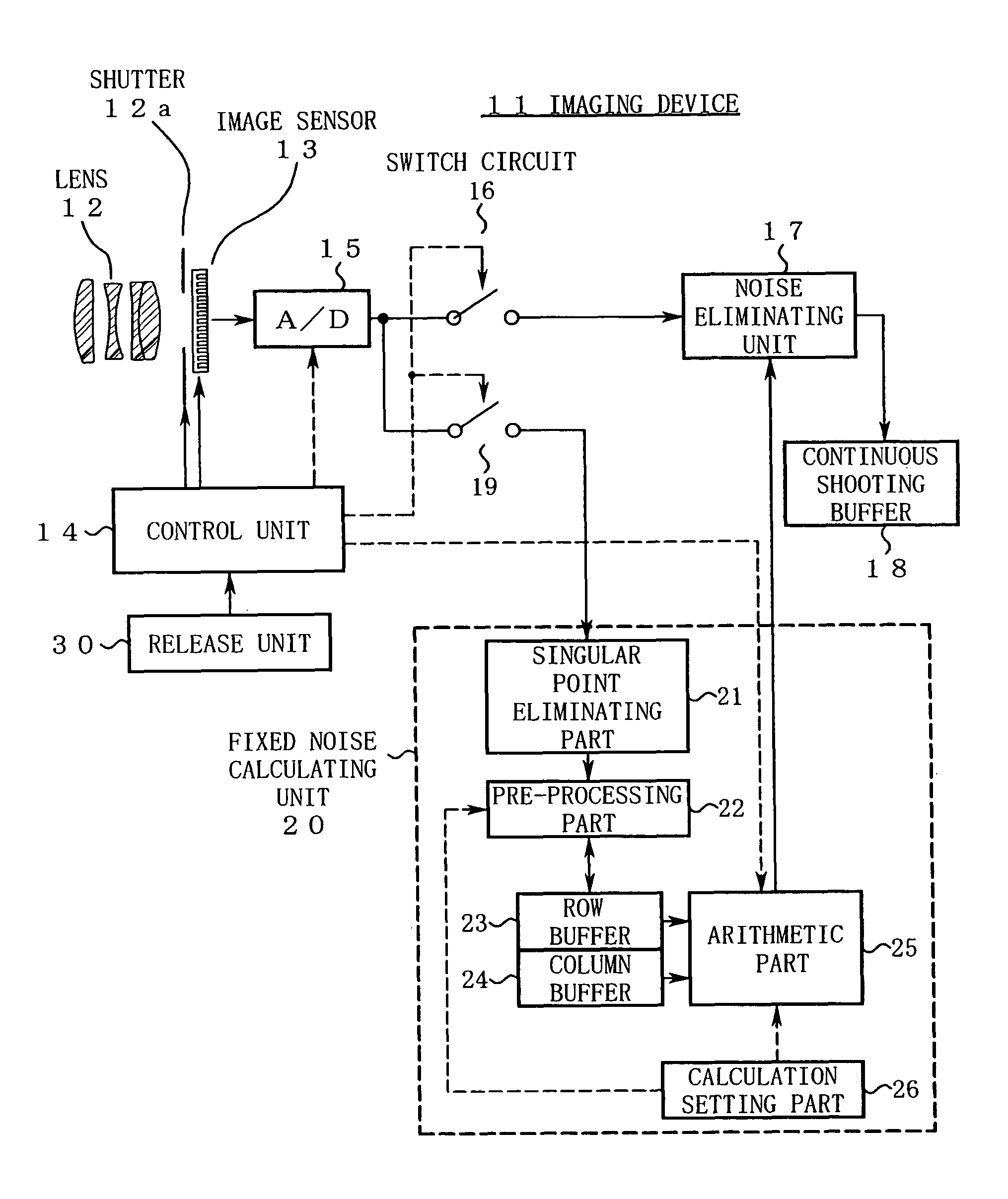
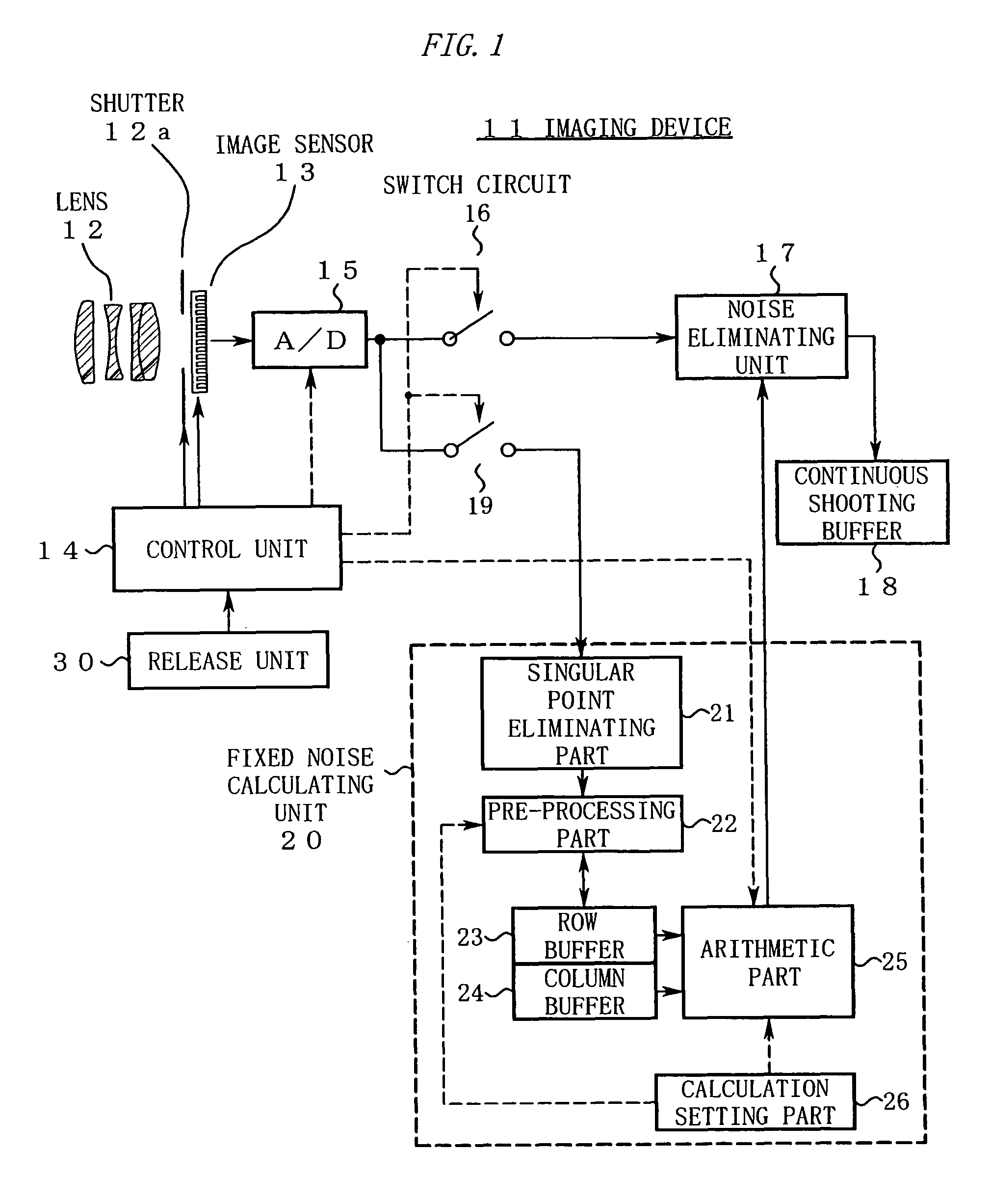
[0034]FIG. 1 is a diagram showing a configuration of an imaging device 11 in a first embodiment.
[0035]In FIG. 1, a lens 12 is attached to the imaging device 11. A shutter 12a and an image sensor 13 are disposed in an image space of the lens 12. A control unit 14 receives a photographing instruction from a release unit 30. In response to this photographing instruction, the control unit 14 performs a control operation so as to drive the shutter 12a and the image sensor 13 and reads from the image sensor 13“a noise output obtained from a partial area (a predetermined row, a predetermined column, or the like) of an available pixel area” and “image data for one screen”.
[0036]A signal thus outputted from the image sensor 13 is inputted to a switch circuit 16 and a switch circuit 19 after being converted to a digital signal in an A / D converting unit 15. The control unit 14 performs changeover control of these switch circuits 16, 19 to divide the...
second embodiment
[0079]FIG. 7 is a diagram showing a configuration of an imaging device 11a in a second embodiment.
[0080]The imaging device 11a is structurally characterized in that the column buffer 24 in the configuration of the first embodiment (FIG. 1) need not be provided. The other configuration is the same as that of the first embodiment (FIG. 1, FIG. 2), and therefore, description of the configuration will be omitted here.
[0081]FIG. 8 is a timing chart illustrating operations of the second embodiment.
[0082]Hereinafter, the operations of the second embodiment will be described in the order of the step number shown in FIG. 8.
Step S11: A user gives a photographing instruction to a control unit 14 by operating a release unit 30.
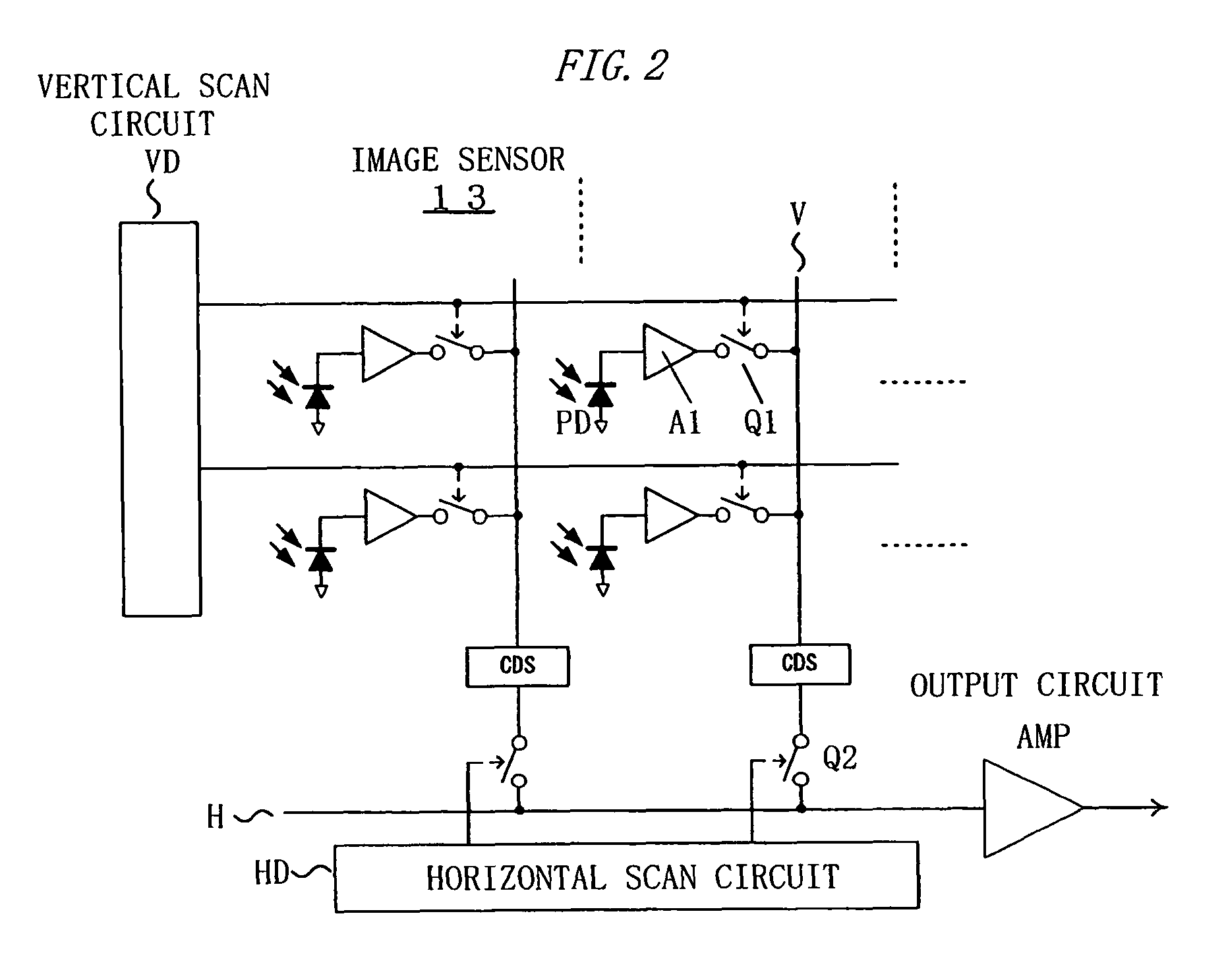
[0083]Step S12: The control unit 14 drives a vertical scan circuit VD and a horizontal scan circuit HD in an image sensor 13 while keeping a shutter 12a closed, and selectively reads noise outputs (dark outputs of photodiodes PD) of predetermined rows shown in FIG. 9[A].
[...
PUM
| Property | Measurement | Unit |
|---|---|---|
| area | aaaaa | aaaaa |
| length of time | aaaaa | aaaaa |
| speed | aaaaa | aaaaa |
Abstract
Description
Claims
Application Information
 - R&D
- Intellectual Property
- Life Sciences
- Materials
- Tech Scout
- Unparalleled Data Quality
- Higher Quality Content
- 60% Fewer Hallucinations
Browse by: Latest US Patents, China's latest patents, Technical Efficacy Thesaurus, Application Domain, Technology Topic, Popular Technical Reports.
© 2025 PatSnap. All rights reserved.Legal|Privacy policy|Modern Slavery Act Transparency Statement|Sitemap|About US| Contact US: help@patsnap.com


