
Capacitive sensor coupling correction

a capacitive sensor and coupling correction technology, applied in the field of touch sensor panels, can solve the problems of parametric capacitive coupling between the connecting traces/metal traces and the sense structures, and achieve the effect of reducing or eliminating the appearance of erroneous touch events

Active Publication Date: 2012-10-30
APPLE INC
View PDF60 Cites 20 Cited by
  • Summary
  • Abstract
  • Description
  • Claims
  • Application Information

AI Technical Summary

Benefits of technology

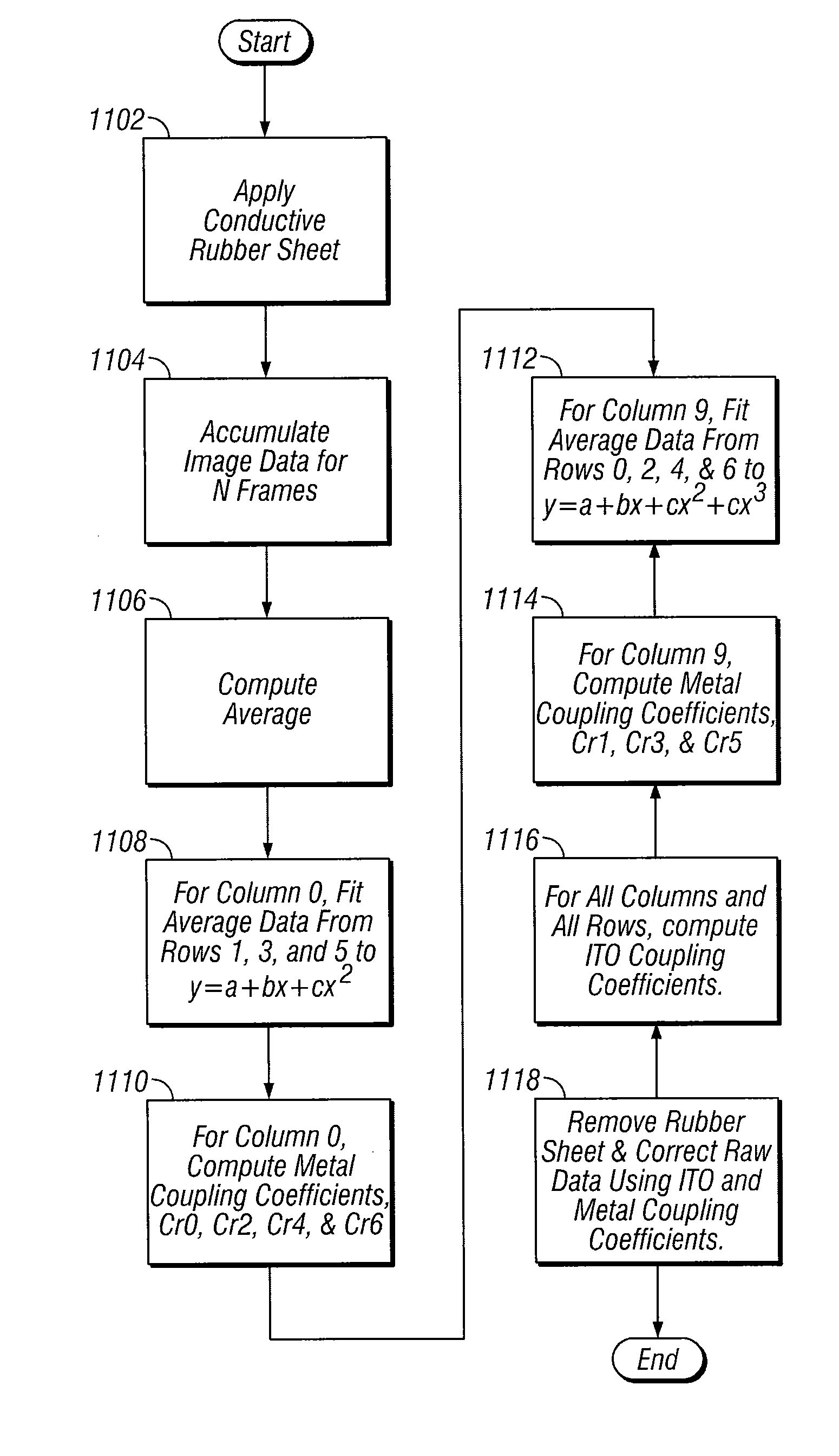
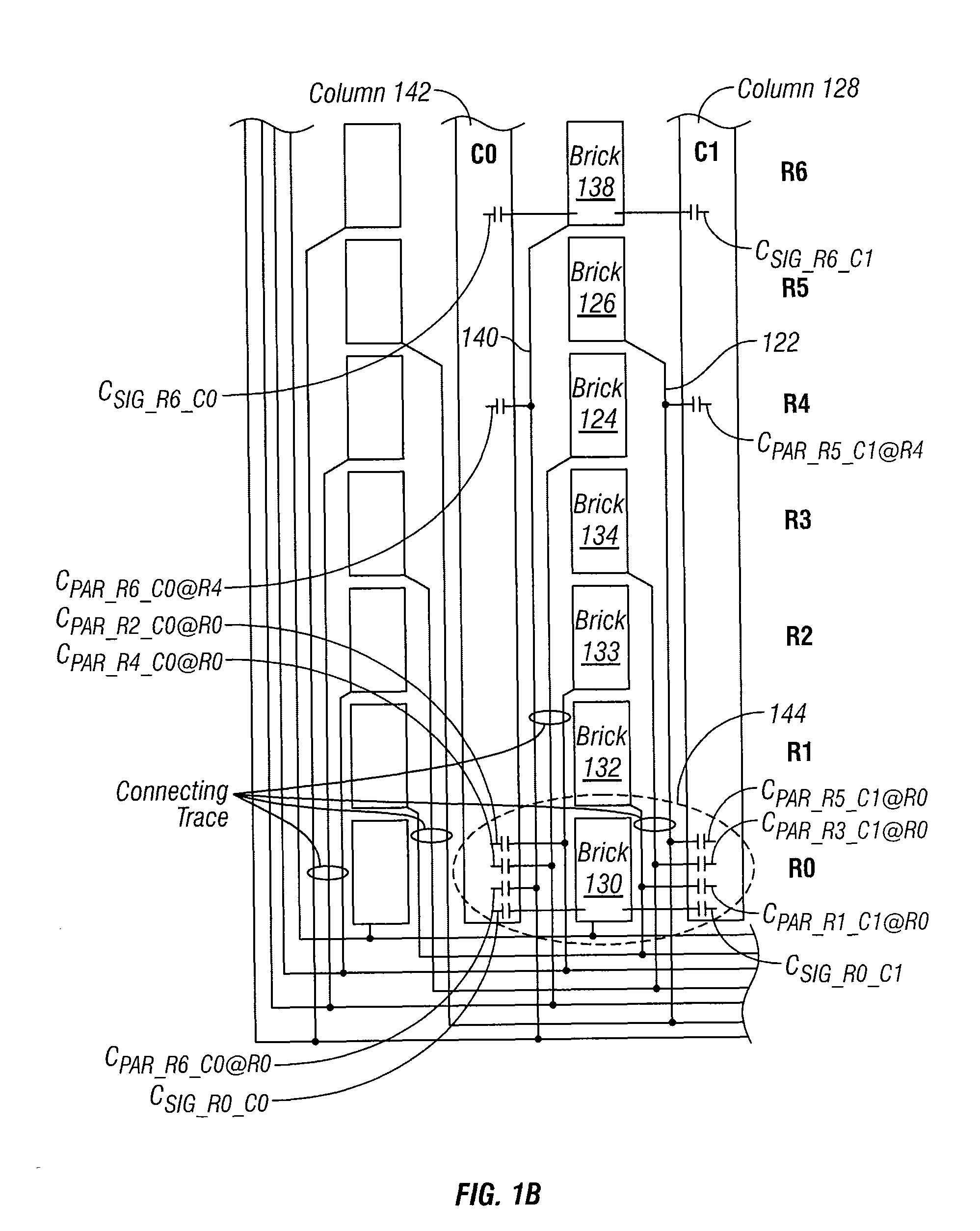
The present invention relates to a method for reducing or eliminating the appearance of erroneous touch events in touch sensor panels caused by parasitic capacitive coupling between connecting traces and metal traces and the sense structures. The method involves calibrating the touch sensor panel by positioning a conductive sheet over the touch surface and measuring sensed signals. Correctional coefficients are then calculated and stored in the device for use during normal operation to determine signal corrections and reduce the impact of parasitic capacitive coupling.

Problems solved by technology

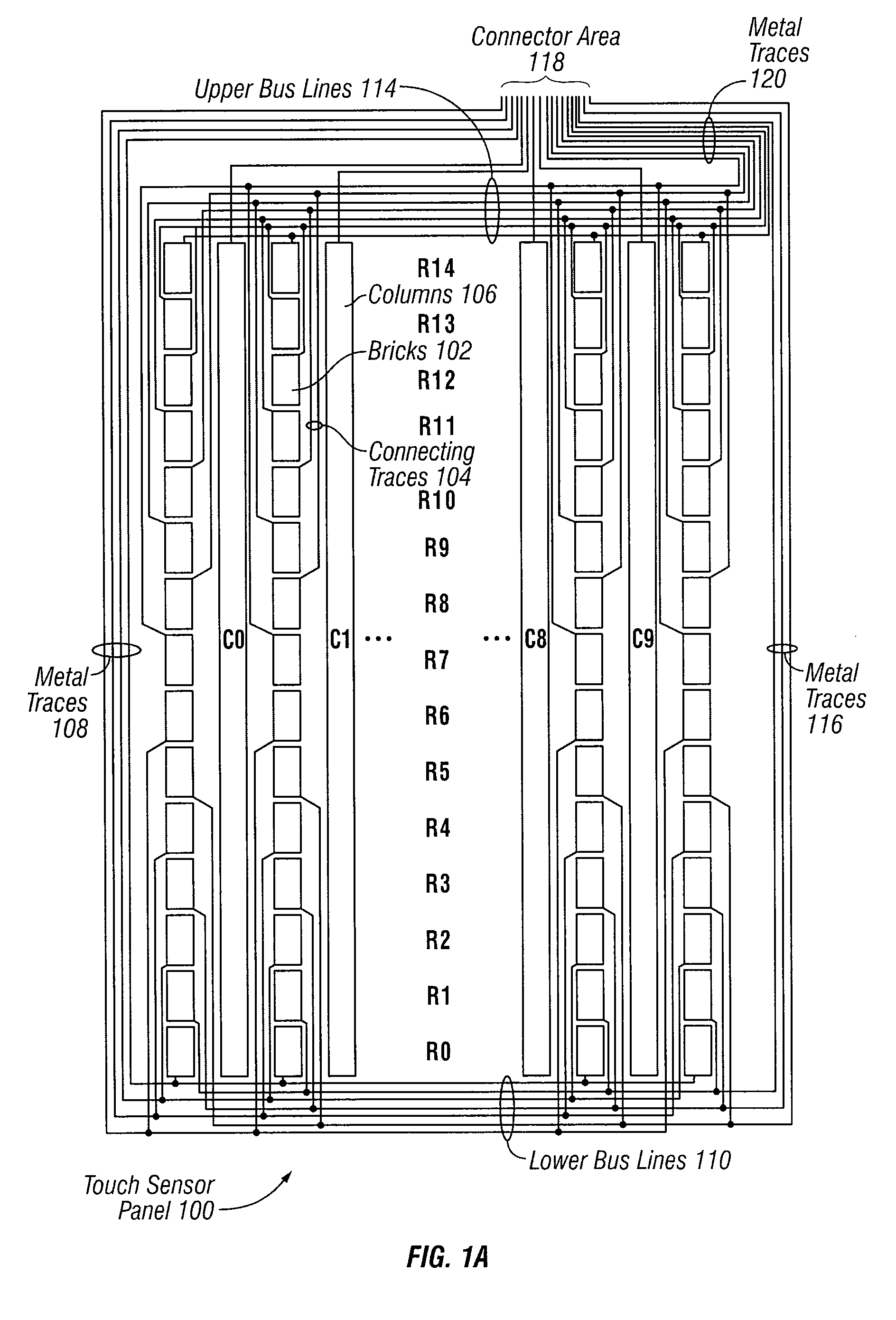
However, because these connecting traces and metal traces may run near or alongside sense structures (e.g. sense columns), parasitic capacitive coupling between the connecting traces / metal traces and the sense structures can occur.

Method used


Image

  • Capacitive sensor coupling correction
  • Capacitive sensor coupling correction
  • Capacitive sensor coupling correction

Examples


Embodiment Construction

[0026]In the following description of preferred embodiments, reference is made to the accompanying drawings which form a part hereof, and in which it is shown by way of illustration specific embodiments in which the invention can be practiced. It is to be understood that other embodiments can be used and structural changes can be made without departing from the scope of the embodiments of this invention.

[0027]Single-sided mutual capacitance touch sensor panels are described in U.S. application Ser. No. 12 / 110,075 entitled “Brick Layout and Stackup for a Touch Screen” filed on Apr. 25, 2008, the contents of which are incorporated herein by reference in their entirety for all purposes. The single-sided restriction of such touch sensor panels can require the use of thin connecting traces in the main area of the touch sensor panel and metal traces in the border areas of the touch sensor panel to provide the necessary connectivity between otherwise isolated drive structures (e.g. row pat...


PUM


Abstract

Methods and apparatus for normalizing the effects of the changes to the parasitic capacitive coupling that can occur in touch sensor panels so as to reduce or eliminate the appearance of erroneous touch events. In some embodiments, at some time prior to regular device use (e.g. during factory calibration), a conductive sheet is initially positioned so as to entirely cover a touch surface of a touch sensor panel. A set of sensed signals may be determined upon driving the drive lines and sensing the sense lines of the panel. Correctional coefficients may then be calculated based in part upon the difference between a sensed signal and an expected signal. The correctional coefficients may then be stored in the device and used to determine signal corrections for a set of measured signals during normal operation.

Description

FIELD OF THE INVENTION[0001]The present invention relates generally to the field of touch sensor panels. More particularly, the present invention is directed in one exemplary aspect to correcting spurious signals generated by changes to parasitic capacitive coupling as a result of a touch event.BACKGROUND OF THE INVENTION[0002]Many types of input devices are presently available for performing operations in a computing system, such as buttons or keys, mice, trackballs, joysticks, touch sensor panels, touch screens and the like. Touch screens, in particular, are becoming increasingly popular because of their ease and versatility of operation as well as their declining price. Touch screens can include a touch sensor panel, which can be a clear panel with a touch-sensitive surface, and a display device such as a liquid crystal display (LCD) that can be positioned partially or fully behind the panel so that the touch-sensitive surface can cover at least a portion of the viewable area of ...

Claims


Application Information

Patent Timeline
Patent Type & Authority Patents(United States)
IPC IPC(8): G06F3/041G06F3/044
CPCG06F3/0418G06F3/044H03K17/9622H03K2217/960705G06F3/0443G06F3/04164G06F3/0446
Inventor ELIAS, JOHN G.HOTELLING, STEVE PORTER
Owner APPLE INC
Learn More