Dithered LEDs to reduce color banding in lensed light fixtures

a technology of leds and light fixtures, which is applied in the direction of fixed installations, lighting and heating apparatus, and ways, can solve the problems of significant alteration of the angular distribution of light from the lens, loss of lumen output, and band average out and be less apparent, so as to reduce or eliminate the appearance, reduce the contrast of bands, and be less visible

Active Publication Date: 2021-01-05
SIMPLY LEDS
View PDF15 Cites 0 Cited by
  • Summary
  • Abstract
  • Description
  • Claims
  • Application Information

AI Technical Summary

Benefits of technology

[0006]In order to reduce or eliminate the appearance of clear and sharply defined color temperature bands at the extreme angles of lenses where the LED is highly magnified, the location and rotation of each LED in an array of multiple LEDs can be carried out so as to blend and “smear” the bands. The Applicant has found that this greatly reduces the contrast of the bands, rendering them less visible. This variation in location and rotation is called spatial and rotational dithering. The Applicant has found that this leads to improved lighting characteristics of LED fixture.
[0007]Each LED is displaced from the center of each lens in the X and / or Y directions by a distance that is approximately half the distance between individual LED die on each LED package. This causes the color temperature bands from each individual LED to mis-align with those of other LEDs, which causes the bands to average out and be less apparent. Additionally, the LEDs are rotated at various angles to blend the bluish die and yellowish spaces rotationally to further overlap and blend the color temperature bands. The result of dithering the LEDs spatially and rotationally is a greatly reduced appearance of color temperature banding without a significant impact on the angular distribution of light from the lens design. The Applicant's methodology incorporating spatial and rotational dithering leads to increased benefits over alternatives such as the application of a diffusing texture which reduces the banding by scattering light, typically resulting in a significant alteration of the angular distribution of light from the lens as well as a loss of lumen output.

Problems solved by technology

This causes the color temperature bands from each individual LED to mis-align with those of other LEDs, which causes the bands to average out and be less apparent.
The Applicant's methodology incorporating spatial and rotational dithering leads to increased benefits over alternatives such as the application of a diffusing texture which reduces the banding by scattering light, typically resulting in a significant alteration of the angular distribution of light from the lens as well as a loss of lumen output.

Method used


Image

  • Dithered LEDs to reduce color banding in lensed light fixtures
  • Dithered LEDs to reduce color banding in lensed light fixtures
  • Dithered LEDs to reduce color banding in lensed light fixtures

Examples


Embodiment Construction

[0021]While the presently disclosed inventive concept(s) is susceptible of various modifications and alternative constructions, certain illustrated embodiments thereof have been shown in the drawings and will be described below in detail. It should be understood, however, that there is no intention to limit the inventive concept(s) to the specific form disclosed, but, on the contrary, the presently disclosed and claimed inventive concept(s) is to cover all modifications, alternative constructions, and equivalents falling within the spirit and scope of the inventive concept(s) as defined in the claims.

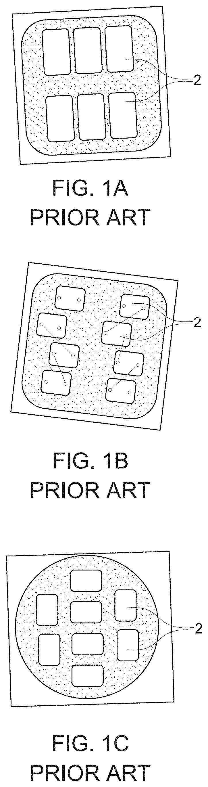
[0022]FIGS. 1a, 1b, and 1c illustrate example configurations of prior art multi-die led packages 2 that are utilized with a lens for lighting purposes for generalized lighting. Example uses of such generalized lighting would be in street or parking lot lights that project light a diffuse manner. These lights are non dithered and provide an aligned appearance either horizontally or verti...


PUM

PropertyMeasurementUnit
color bandingaaaaaaaaaa
distanceaaaaaaaaaa
areaaaaaaaaaaa

Abstract

An improved multi-die LED lighting apparatus for use with a lens that facilitates light dispersion while minimizing color banding and maintaining the light distribution intent of the design of the lens. The individual LED die are dithered, both rotationally and spatially relative to neighboring LED dies to minimize color banding of the LED lighting apparatus. The result is an reduction in color banding while seeking to retain the original light dispersion intent of the lens.

Description

PRIORITY / CROSS-REFERENCE TO RELATED APPLICATIONS[0001]This application claims the benefit of U.S. Provisional Application No. 62 / 805,831, filed Feb. 14, 2019, the disclosure of which is incorporated by reference.TECHNICAL FIELD[0002]The presently disclosed and claimed technology generally relates to an improved a light emitting diode (LED) die arrangement and method for creating an improved light emitting diode die arrangement for decreasing color banding in light dispersion applications, and more particularly to improved light dispersion characteristics in decreasing color banding between neighboring LED dies in multi-die LED arrays.BACKGROUND[0003]Multi die LED lights typically comprise a plurality of LED dies affixed to a printed circuit board. The LED dies and the printed circuit board are often referred to as a Printed Circuit Assembly (PCA). The multi dies are typically affixed to the circuit board in rows and columns with minimal variation. LEDs that are made up of multiple d...

Claims


Application Information

Patent Timeline
Patent Type & Authority Patents(United States)
IPC IPC(8): F21K9/69H01L25/13F21K9/90F21S8/08H01L33/58F21V5/00F21W111/02F21Y115/10F21Y105/12
CPCF21K9/69F21K9/90F21S8/085F21V5/007H01L25/13H01L33/58F21W2111/02F21Y2105/12F21Y2115/10F21K9/00F21W2131/103H01L25/0753
Inventor WILKINSON, DEAN A.
Owner SIMPLY LEDS
Why Eureka
Try Eureka