
Bi-modal turbine assembly and starter / drive turbine system employing the same

a technology of starter/drive turbine and turbine assembly, which is applied in the direction of engine starter, turbine/propulsion engine ignition, machines/engines, etc., can solve the problems of net energy loss and production of high forward thrus

Active Publication Date: 2012-10-23
HONEYWELL INT INC
View PDF17 Cites 51 Cited by
  • Summary
  • Abstract
  • Description
  • Claims
  • Application Information

AI Technical Summary

Benefits of technology

The bi-modal turbine system efficiently manages energy distribution between propulsion and electrical loads, enhancing electrical output during low engine speeds and reducing overall system weight and cost by replacing conventional air turbine starters.

Problems solved by technology

Although the speed of the gas turbine engine may be increased to augment the electrical output of the generator, this typically results in the production of a high forward thrust.
The forward thrust may be reduced by dumping a portion of the air discharged from the gas turbine engine's turbine or turbines overboard; however, this practice still results in a net energy loss and is consequently inefficient.

Method used


Image

  • Bi-modal turbine assembly and starter / drive turbine system employing the same
  • Bi-modal turbine assembly and starter / drive turbine system employing the same
  • Bi-modal turbine assembly and starter / drive turbine system employing the same

Examples


Embodiment Construction

[0012]The following Detailed Description is merely exemplary in nature and is not intended to limit the invention or the application and uses of the invention. Furthermore, there is no intention to be bound by any theory presented in the preceding Background or the following Detailed Description.

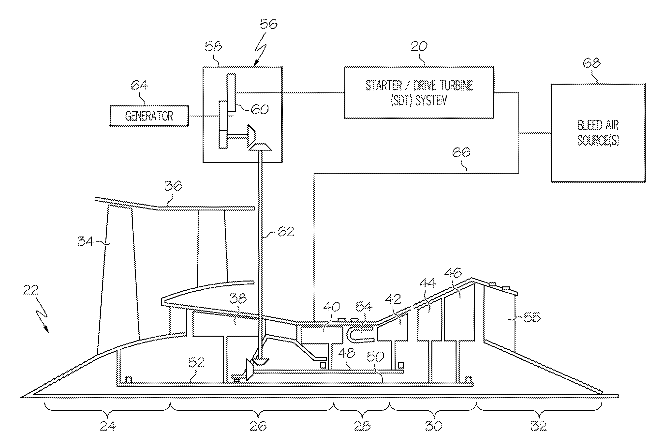
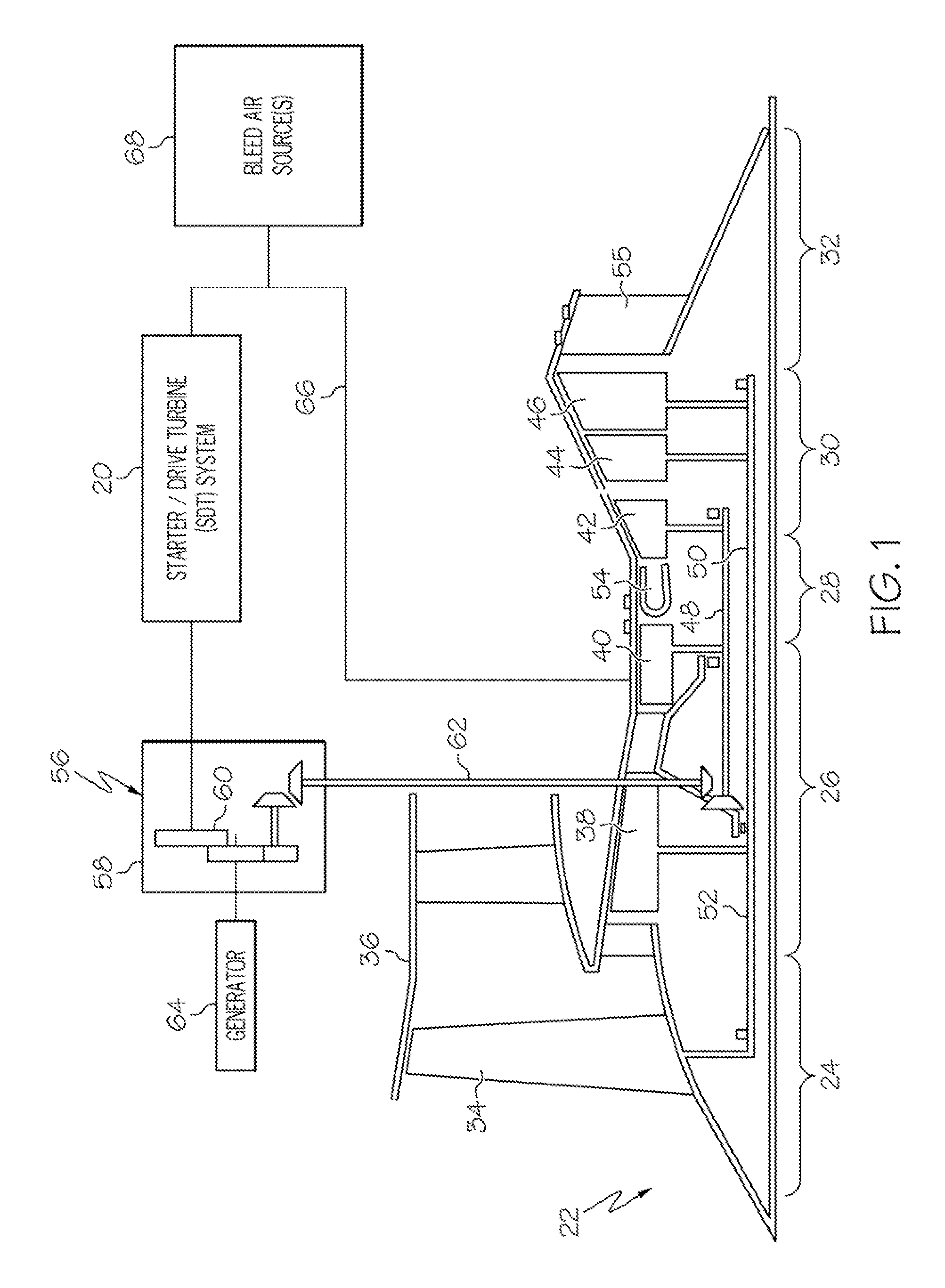
[0013]FIG. 1 is a functional schematic of a starter / drive turbine (SDT) system 20 deployed in conjunction with a gas turbine engine 22 in accordance with an exemplary embodiment. As a non-limiting example, gas turbine engine 22 is illustrated in FIG. 1 as a three spool turbofan engine including an intake section 24, a compressor section 26, a combustion section 28, a turbine section 30, and an exhaust section 32. Intake section 24 includes a fan 34 mounted in a fan case 36. Compressor section 26 includes one or more compressors (e.g., an intermediate pressure (IP) compressor 38 and a high pressure (HP) compressor 40), and turbine section 30 includes one or more turbines (e.g., an HP turbine ...


PUM


Abstract

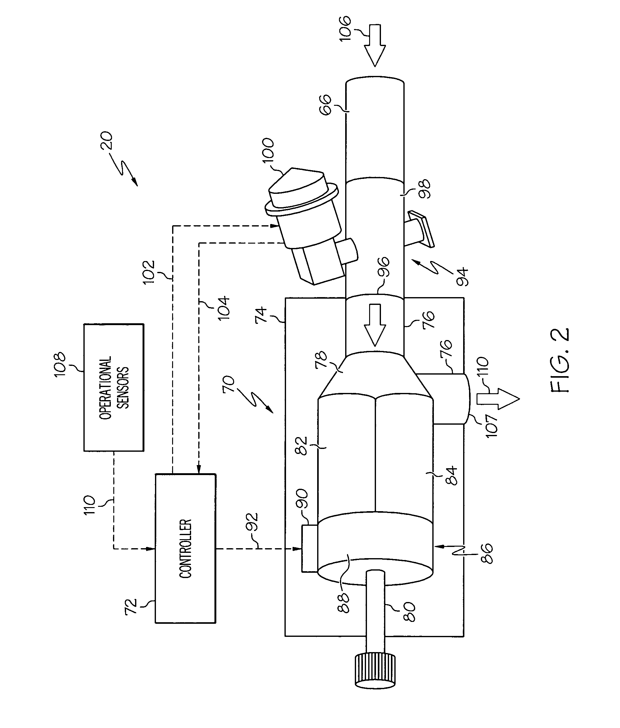
A bi-modal turbine assembly is provided for use in conjunction with a gas turbine engine. In one embodiment, the bi-modal turbine assembly includes a housing assembly having a flow passage therethrough, a turbine wheel rotatably mounted in the housing assembly and positioned so as to be driven by pressurized air flowing through the flow passage, an output shaft rotatably mounted in the housing assembly, and first and second gear trains disposed in the housing assembly. A switching device is also disposed in the housing assembly and configured to mechanically couple: (i) the first gear train between the turbine wheel and the output shaft in a first operational mode, and (ii) the second gear train between the turbine wheel and the output shaft in a second operational mode.

Description

TECHNICAL FIELD[0001]The present invention relates generally to aircraft propulsion systems and, more particularly, to a starter / drive turbine system employing a bi-modal turbine assembly suitable for extracting power from a gas turbine engine.BACKGROUND[0002]An air turbine starter (ATS) is a well-known device utilized to initiate spool rotation of an aircraft's gas turbine engine during main engine start (MES). A generalized ATS includes a housing assembly having a flow passage therethrough, a turbine wheel rotatably mounted in the housing assembly, an ATS output shaft, and a gear train mechanically coupled between the turbine wheel and the output shaft. Notably, the ATS housing assembly may comprise multiple individual housings or modules fixedly joined together. These housing may include, for example, a turbine module housing containing the turbine wheel. The ATS output shaft is mechanically coupled to a spool (e.g., the high pressure spool) of a gas turbine engine through an acc...

Claims


Application Information

Patent Timeline
Patent Type & Authority Patents(United States)
IPC IPC(8): F02C7/277F02C7/32F02C6/08
CPCF02C6/08F02C7/277F02C7/32Y02T50/671F05D2260/85Y02T50/60
Inventor LIBERA, TONYZEINER, PETER
Owner HONEYWELL INT INC
Learn More