
Method of operating a gas turbine power plant

a gas turbine and power plant technology, applied in the direction of engines/engines, engine starters, turbine/propulsion engine ignition, etc., can solve the problems of limiting the operational life, stalling of compressors, and instabilities of compressors, so as to reduce or eliminate the risk of compressor instabilities

Inactive Publication Date: 2012-10-23
ANSALDO ENERGIA IP UK LTD
View PDF6 Cites 3 Cited by
  • Summary
  • Abstract
  • Description
  • Claims
  • Application Information

AI Technical Summary

Benefits of technology

This approach effectively reduces rotational stall and shaft vibrations, minimizing the risk of compressor damage and enhancing cooling, thus prolonging the operational lifetime of gas turbines.

Problems solved by technology

It is generally known that during the shut down of a gas turbine, compressor instabilities can occur.
In particular, stalls can occur in the compressor once lower speeds are reached.
Such stalls can give rise to vibrations of the airfoils and shaft, which potentially limit the operational lifetime or lead to compressor damage.
Maintaining that a setting of vane positions as a function of rotor speed leads to unsatisfactory operation, it presents in particular a method of positioning the stator vanes together with a regulation of compressor bypass valves.
This condition can lead to a stalling of blades counter to the direction of rotation of the shaft and unstalling of blades in the direction of shaft rotation.
This results in a stall cell rotating at approximately 50% of the shaft speed and can lead to high shaft vibrations peaks when the shaft imbalance caused by the stall conditions coincides with a critical eigenfrequency of the shaft.
During a shut down according to an exemplary method, the compressor airfoils have an aerodynamic braking effect on the shaft, which results in a compressor pressure rise across the airfoil stages.

Method used


Image

  • Method of operating a gas turbine power plant
  • Method of operating a gas turbine power plant
  • Method of operating a gas turbine power plant

Examples


Embodiment Construction

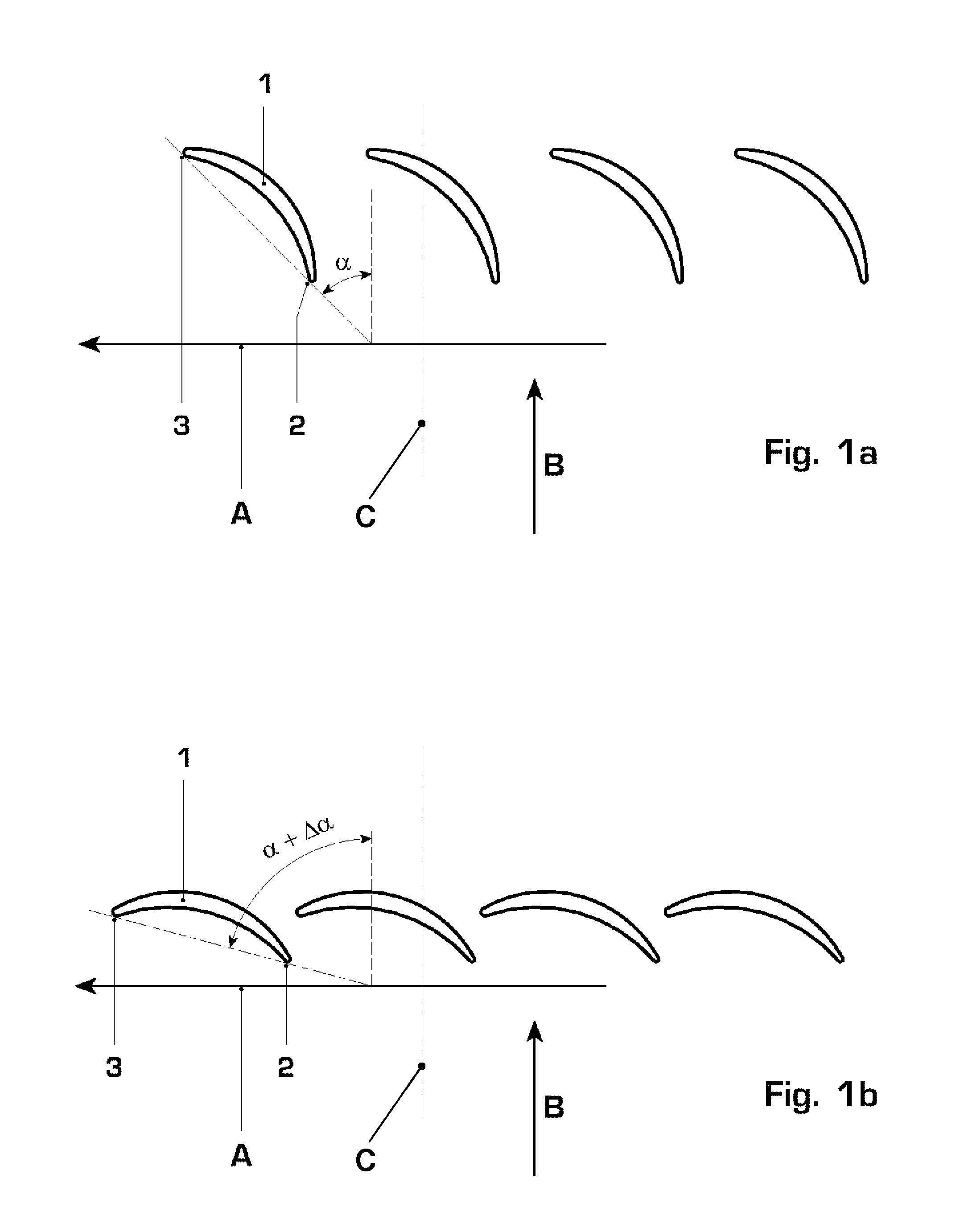
[0024]In an exemplary method embodying principles of the invention, the gas turbine is decelerated from full speed. At a shaft speed 5%, preferably 10%, above the shaft speed where a vibration peak occurs, closure of the inlet guide vanes is initiated. The speed at which closure is initiated is, for example, at a speed in the range between 44% and 60% of the full shaft speed, where the actual speed depends on the ambient air temperature and the type of gas turbine. In one particular example the onset is at 48% of the full shaft speed. Preferably, the onset of closure should be as late as possible, however prior to entering the stall regime. Effectively, the closure should be initiated such that closure of the vanes is complete before the critical speed is reached at which rotational stall can occur.

[0025]For the closure of the inlet guide vanes, the guide vanes of the first stage or first stages of the compressor are rotated from initial position before rotor deceleration such that ...


PUM


Abstract

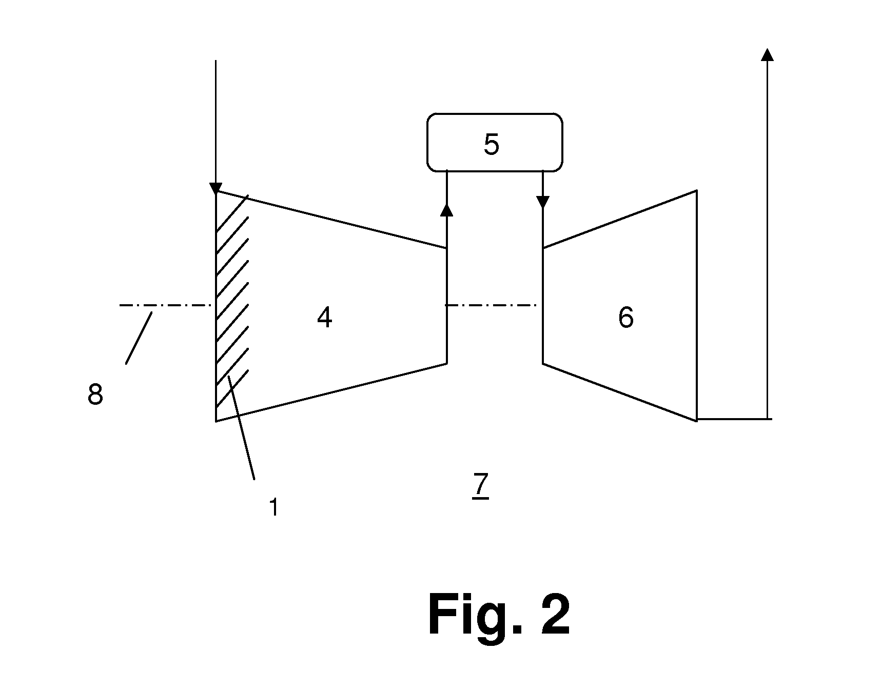
In a method of operating a gas turbine during shut down, the gas turbine is decelerated and closure of compressor inlet guide vanes (1) is initiated at a shaft speed at least 5% above the shaft speed where a vibration peak occurs. The compressor inlet guide vanes (1) are closed by an angle in the range from 15°-35°, preferably at a rate between 5° and 10° per second. The method effects a reduction of the risk of rotational stall.

Description

[0001]This application is a Continuation of, and claims priority under 35 U.S.C. §120 to, International application no. PCT / EP2007 / 052183, filed 8 Mar. 2007, and claims priority under 35 U.S.C. §§119, 365 therethrough to European application No. 06111737.0, filed 27 Mar. 2006, the entireties of which are incorporated by reference herein.BACKGROUND OF THE INVENTION[0002]1. Field of the Invention[0003]The invention relates to a method of operating a gas turbine power plant and in particular to a method for the operation of the gas turbine power plant during plant shut down by regulating stator vanes of a multistage axial air compressor.[0004]2. Brief Description of the Related Art[0005]It is generally known that during the shut down of a gas turbine, compressor instabilities can occur. In particular, stalls can occur in the compressor once lower speeds are reached. Such stalls can give rise to vibrations of the airfoils and shaft, which potentially limit the operational lifetime or le...

Claims


Application Information

Patent Timeline
Patent Type & Authority Patents(United States)
IPC IPC(8): F02C9/00
CPCF01D5/10F01D9/041F01D9/042F01D17/162F01D21/06F01D25/246F02C9/22F02C9/54F04D27/0246F04D27/0261Y02T50/673Y02T50/60Y02B30/70
Inventor MATZ, CHARLESERB, BERNHARDDAS BURMA, BIKASBERESINI, LUCATREIBER, MARTIN HEINRICHMARX, PETER
Owner ANSALDO ENERGIA IP UK LTD
Learn More