
Methods for abluminally coating medical devices

a technology of medical devices and abluminally coating, which is applied in the direction of prosthesis, pharmaceutical packaging, large fixed members, etc., can solve the problems of drug coating material interference, drug coating chipping, and damage to the underlying coating

Inactive Publication Date: 2012-10-23
BOSTON SCI SCIMED INC
View PDF20 Cites 99 Cited by
  • Summary
  • Abstract
  • Description
  • Claims
  • Application Information

AI Technical Summary

Benefits of technology

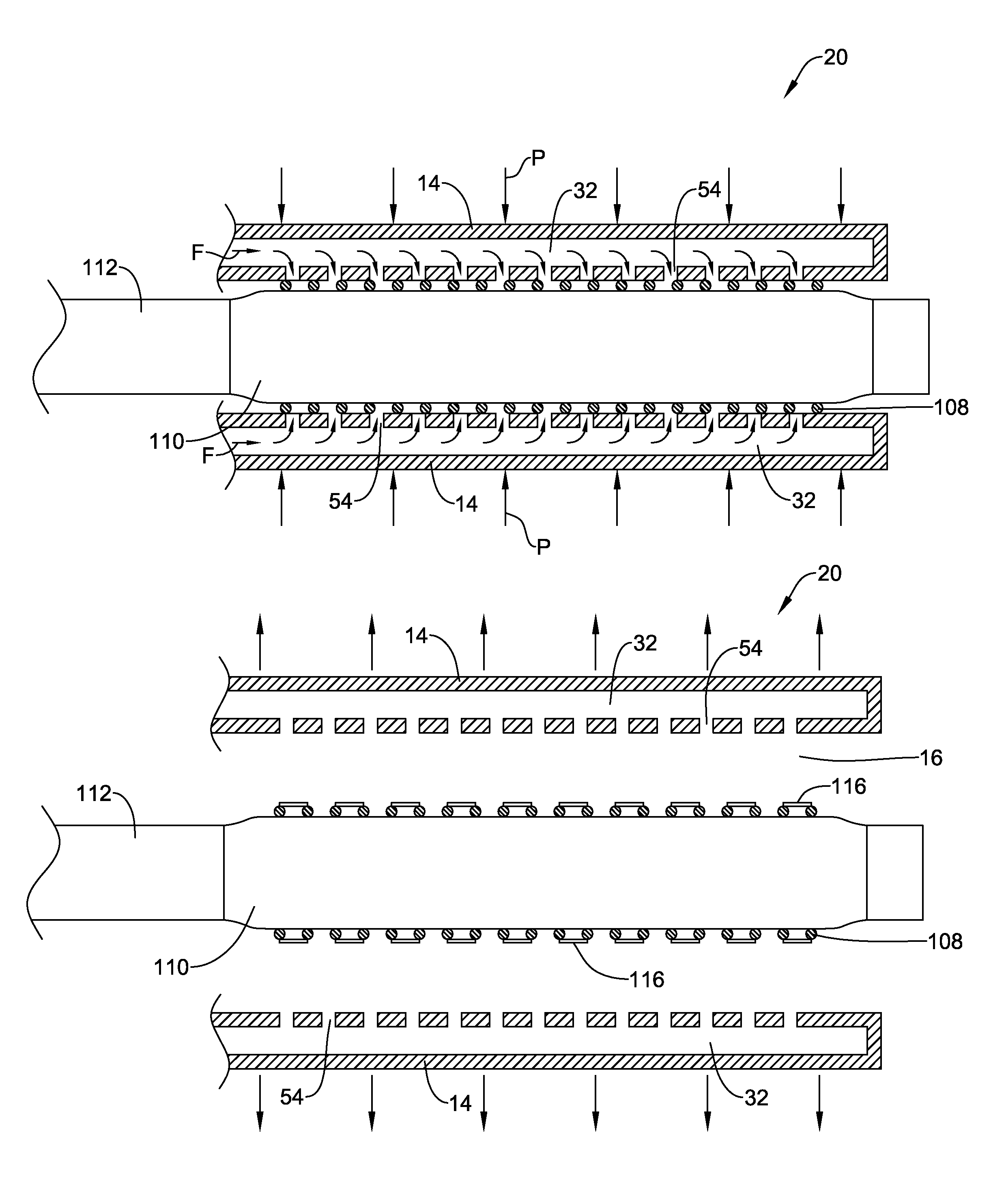
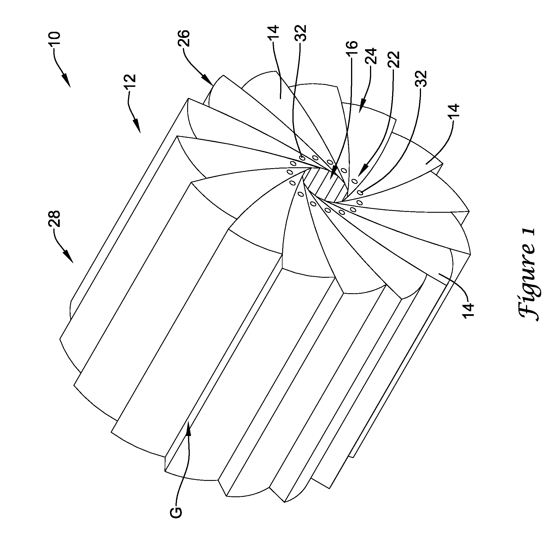
The present patent is about a device and method for coating medical devices, such as stents, with a drug coating material. The device includes a crimping apparatus with movable crimping blades that form a lumen for crimping the stent onto a balloon catheter. The crimping blades have openings that allow fluid to be delivered to the stent during crimping. The method involves positioning the stent and balloon in the crimping lumen, crimping the stent onto the balloon, and then removing the crimped stent and balloon from the crimping lumen. The technical effect of this patent is to provide a way to efficiently and effectively coat stents with drug coating materials during the crimping process.

Problems solved by technology

In some cases, the application of pressure to the stent during the crimping process may interfere with the drug coating material.
The loading of the stent onto the balloon catheter may result in frictional forces exerted on the stent that can cause damage to the underlying coating on the stent, in some cases resulting in chipping of the drug coating.
The application of heat to the stent may also cause changes in the chemical composition of the drug coating material and may create thermal cracks in the coating, limiting the types of drug coatings that can be used.

Method used


Image

  • Methods for abluminally coating medical devices
  • Methods for abluminally coating medical devices
  • Methods for abluminally coating medical devices

Examples


Embodiment Construction

[0025]The following detailed description should be read with reference to the drawings. The drawings, which are not necessarily to scale, depict illustrative embodiments and are not intended to limit the scope of the disclosure. Although examples of construction, dimensions, and materials are illustrated for the various elements, those skilled in the art will recognize that many of the examples provided have suitable alternatives that may be utilized. Moreover, while the illustrative apparatuses and methods are described with respect to the coating of stents and crimping of stents onto a balloon of a stent delivery catheter, it should be understood that other medical devices may benefit from one or more of the features disclosed herein. Examples of other medical devices can include, but are not limited to, grafts, stent-grafts, and vena-cava filters.

[0026]Referring now to FIG. 1, an illustrative crimping apparatus 10 in accordance with an illustrative embodiment will now be describe...


PUM

PropertyMeasurementUnit
lengthaaaaaaaaaa
lengthaaaaaaaaaa
distanceaaaaaaaaaa

Abstract

A stent crimping and coating apparatus is disclosed. The apparatus includes a plurality of crimping blades positioned in a radial array and collectively forming a central crimping lumen, wherein the plurality of crimping blades radially movable to alter the diameter of the central crimping lumen. Each of the crimping blades includes a first surface configured to at least in part define the central crimping lumen. One or more of the crimping blades includes a fluid channel extending therein and a plurality of openings in fluid communication with the fluid channel. The plurality of openings are located at the first surface of the one or more crimping blades and adapted to discharge a fluid into the central crimping lumen.

Description

FIELD[0001]The present disclosure relates generally to the field of coating and crimping stents or other medical devices. More specifically, the present disclosure pertains to apparatus and methods for abluminally coating stents or other medical devices mounted onto a delivery device.BACKGROUND[0002]Medical devices such as stents, stent grafts, and vena cava filters are often utilized in combination with a delivery device for placement at a desired location within the body. A medical prosthesis such as a stent, for example, may be loaded onto a stent delivery device such as a balloon catheter and then introduced into the lumen of a body vessel in a configuration having a reduced diameter. Once delivered to a target location within the body, the stent may then be expanded to an enlarged configuration within the vessel to support and reinforce the vessel wall while maintaining the vessel in an open, unobstructed condition. In some medical procedures such as a percutaneous transluminal...

Claims


Application Information

Patent Timeline
Patent Type & Authority Patents(United States)
IPC IPC(8): B21D39/00A61F2/06
CPCA61F2/95A61F2002/9522A61F2250/0067B05D2254/02Y10T29/49929Y10T29/53996Y10T29/49913Y10T29/49885Y10T29/49888Y10T29/49982Y10T29/49927A61F2/9522A61F2/9524
Inventor EIDENSCHINK, TRACEE E. J.HEIDNER, MATT
Owner BOSTON SCI SCIMED INC
Learn More