
Cushion clip

a technology of cushion and clip, which is applied in the field of cushion clips, can solve the problems of inability to smoothly close the door, noise generation, and the door cannot be sufficiently prevented from vibrating, and achieve the effects of easy projection, increased reacting force, and easy projection

Active Publication Date: 2012-10-23
DAIWA KASEI IND CO LTD
View PDF14 Cites 18 Cited by
  • Summary
  • Abstract
  • Description
  • Claims
  • Application Information

AI Technical Summary

Benefits of technology

The cushion clip effectively absorbs impact and generates a consistent reaction force over a wide range of compression, preventing vibration and noise while maintaining the lock device's integrity by adjusting the projection's height and using soft and hard resin materials for optimal deformation and stability.

Problems solved by technology

One drawback of not having the characteristics described above include, for example, that the door of the glove box cannot be sufficiently prevented from vibrating.
This may lead to noise generation.
Further, the door cannot be smoothly closed.
When the cushion clip is compressed until the maximum reaction force can be generated, a lock device of the door cannot be easily unlocked.
Further, when the cushion clip is further compressed until a reaction force greater than the maximum reaction force is generated, the lock device of the door is subjected to an excessive load.
This may lead to malfunction of the lock device.
As a result, a range of amount of compression in which desired reaction force can be generated is very narrow.
Therefore, the cushion clip 101 cannot generate the desired reaction force over a wide range of the amount of compression.
Further, because a diameter of the projection 190 is thin, the projection 190 cannot work well as a stopper and cannot prevent interference between the door and the glove box.

Method used


Image

  • Cushion clip
  • Cushion clip
  • Cushion clip

Examples


Embodiment Construction

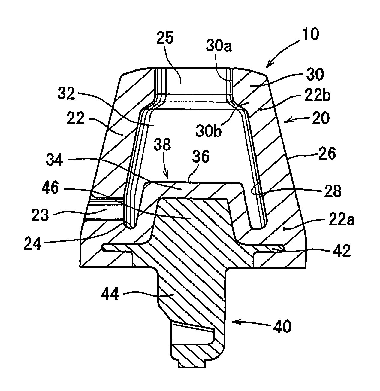
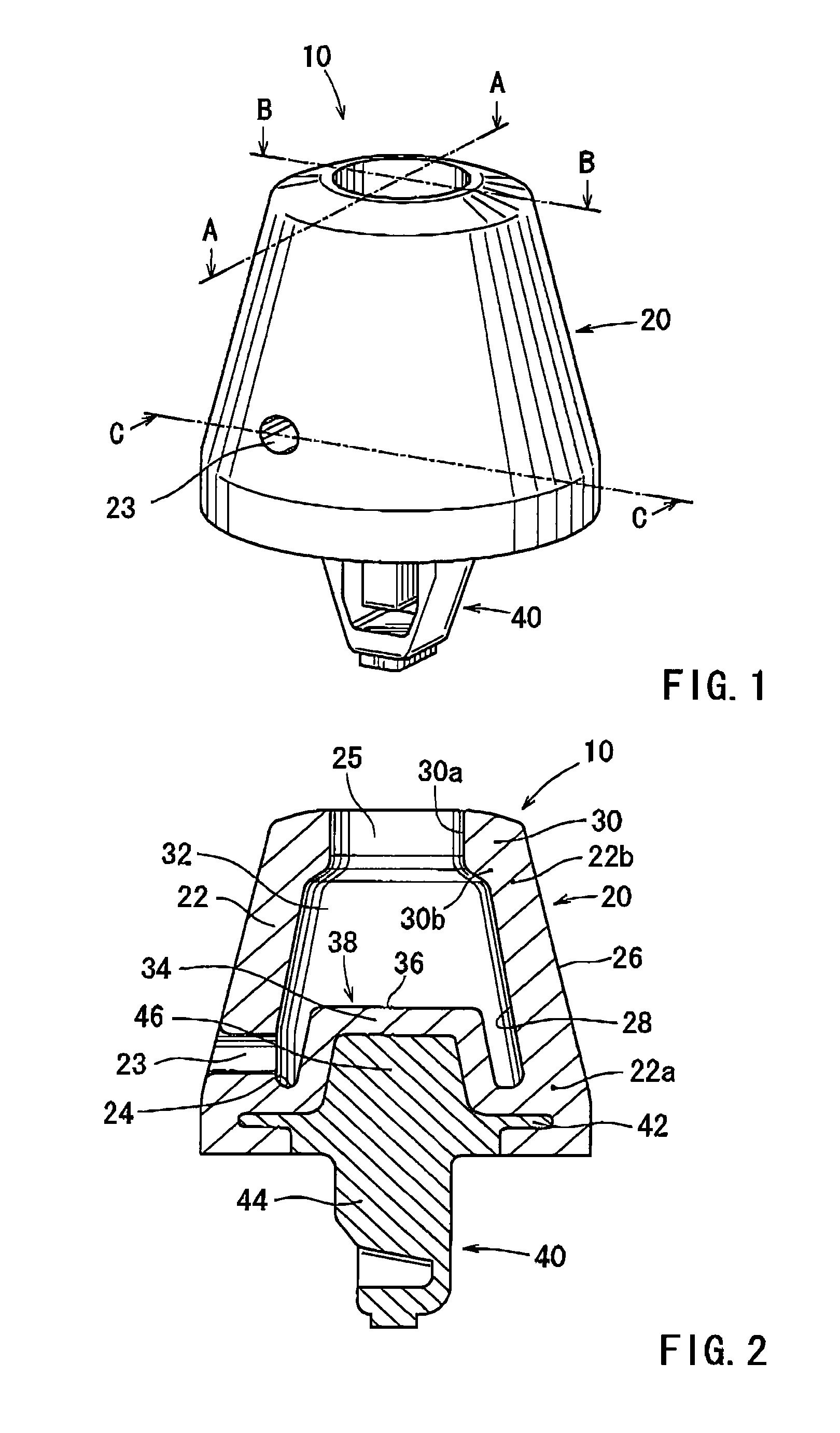
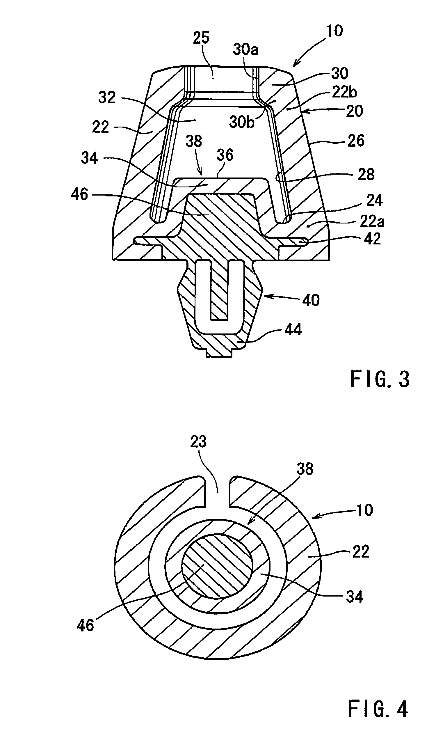
[0060]Examples will be described with reference FIGS. 1 to 13 and 15-20.

[0061]U.S. application Ser. No. 12 / 686,515 filed on Jan. 13, 2010 and assigned to the same assignee as the present application discloses a cushion clip 210 shown in FIG. 17, and its contents are herein entirely incorporated by reference. The cushion clip 210 may preferably be positioned between a box main body 250 of a glove box of a vehicle and a cover or door 254 of the glove box while the cushion clip 210 is secured to the box main body 250, so as to absorb an impact that can be produced when the door 254 is closed. The cushion clip 210 is composed of a cushioning portion 220 that is capable of absorbing the impact, and an engagement portion 240 that is capable of engaging with an attachment hole 252 formed in the box main body 250. The cushioning portion 220 and the engagement portion 240 may preferably be integrated with each other.

[0062]As shown in FIG. 16, the cushioning portion 220 of the cushion clip 21...


PUM


Abstract

A cushion clip includes a hollow cushioning portion, an engagement portion and a projection. The cushioning portion has a bottom wall portion and a side wall portion, and the side wall portion has cone-shaped outer and inner surfaces that are tapered from a proximal end toward a distal end thereof. The side wall portion has a top portion that is formed in the distal end thereof, and the top portion has an inner periphery radially inwardly protruding from the side wall portion and defining the central opening therein. The projection is cylindrically projected from the bottom wall portion toward the central opening of the cushioning portion, and has an upper end portion which diameter is larger than or equal to a diameter of the opening.

Description

[0001]This application claims priority to Japanese patent application serial number 2009-175175, filed on Jul. 28, 2009.BACKGROUND OF THE INVENTION[0002]1. Field of the Invention[0003]The present invention relates to a cushion clip. More particularly, the present invention relates to a cushion clip that is attached to an attachment hole formed in a stationary member while the cushion clip is positioned between the stationary member and a movable member so as to absorb an impact that can be produced when the movable member moves toward the stationary member.[0004]2. Description of Related Art[0005]This type of cushion clip is already known. Generally, in such a cushion clip, a cushioning portion that is capable of absorbing an impact is integrated with an engagement portion that is capable of engaging with an attachment hole formed in a stationary member. Further, in the cushion clip thus constructed, the cushioning portion is formed of a soft resin material and has a hollow and subs...

Claims


Application Information

Patent Timeline
Patent Type & Authority Patents(United States)
IPC IPC(8): E05F5/00
CPCF16B21/086F16B21/088F16F1/44E05F5/022Y10T24/44026Y10T24/44983Y10T16/628
Inventor UKAI, JUNYAIWAHARA, TOSHIOYAMAMOTO, REIKOTAKEMOTO, MINORU
Owner DAIWA KASEI IND CO LTD
Learn More