
Adjustable multifocal intraocular lens system

a multi-focal, intraocular lens technology, applied in the field of multi-focal intraocular lens, can solve the problems of traumatic laser exchange procedure, surgical changes to the eye, patient with some refractive error, etc., and achieve the effect of preserving presbyopia treatment and enhancing iol us

Inactive Publication Date: 2012-10-16
PORTNEY VALDEMAR
View PDF7 Cites 41 Cited by
  • Summary
  • Abstract
  • Description
  • Claims
  • Application Information

AI Technical Summary

Benefits of technology

The system effectively manages multifocal dysphotopsia by substantially masking near power, enabling precise sphero-cylinder refraction correction and improved image contrast, reducing the need for invasive procedures and ensuring predictable visual outcomes.

Problems solved by technology

The problem arises in viewing far bright object at low light condition as the light that passes through the near focus of the multifocal optic creates out of focus image of this far bright object and is perceived by the patient as a halo around the image of the bright source formed by light passing through far focus.
The halos are commonly tolerable but in some instances create too much vision disturbance leading to the multifocal lens exchange with a monofocal IOL which eliminates the presence of near focus.
The lens exchange is highly traumatic procedure.
It is also the procedure that commonly leaves patient with some refractive error because of the uncertainty with power calculation of the exchange monofocal lens and induces surgical changes to the eye due to highly invasive surgical procedure itself.
Though the instance of severe multifocal dysphotopsia is fairly small, it is not predictable prior to the surgery which patient may experience it.
In short, multifocal dysphotopsia is unpredictable thus creating a significant issue for multifocal IOL use by the surgeons and issue for the patients who may end up with the lens exchange.

Method used


Image

  • Adjustable multifocal intraocular lens system
  • Adjustable multifocal intraocular lens system
  • Adjustable multifocal intraocular lens system

Examples


Embodiment Construction

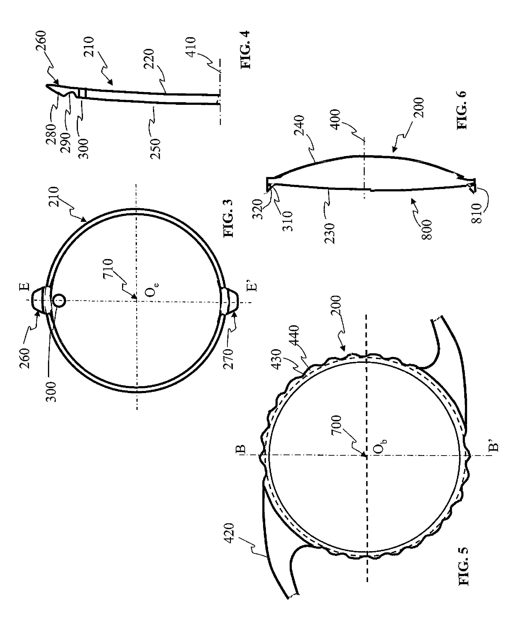
[0051]FIG. 1 is a portion of cross-section of the adjustable multifocal intraocular lens system of the present invention with refraction multifocal power. The refraction multifocal surface is a combination of flatter and steeper regions of the surface of different curvatures to produce lower and higher powers for distance, near and / or intermediate vision, i.e. flatter portion is usually corresponds to far power and steeper portion is usually corresponds to intermediate or near power.

[0052]Base multifocal refraction IOL 100 is thus configured to provide the multifocal vision correction which is close as possible to the required far vision and also providing the range of vision from far to near, i.e. it includes near power in addition to far power. Since enhance multifocal IOL 110 is configured to provide only a small diopter correction to the base IOL, it may be provided with a spherical power of between about −3.0 and +3.0 diopters and / or; a cylinder power of between about −10.0 and...


PUM

PropertyMeasurementUnit
distanceaaaaaaaaaa
central thicknessaaaaaaaaaa

Abstract

An adjustable multifocal intraocular lens system for an individual's eye, includes a base multifocal intraocular lens having an optic with an optical axis, a peripheral edge, a multifocal optical power anterior surface and a posterior surface along with an attachment for maintaining the base multifocal lens in the individual's eye with the optical axis centered along an eye optical axis. An enhanced multifocal intraocular lens is provided with an optic with a peripheral edge, an anterior surface and a reverse multifocal optical power posterior surface, and a coupling enables assembly of the base lens and enhance lens with the enhance lens posterior surface overlaying the base lens anterior surface in order that the enhance intraocular lens reverse multifocal surface adjust multifocal powers of the base IOL by substantially masking near power of the base multifocal intraocular lens.

Description

[0001]The present application claims priority from U.S. Ser. No. 61 / 264,004 filed Nov. 24, 2009. This referenced application is to be incorporated into the present application in its entirety.FIELD OF THE INVENTION[0002]The present invention relates generally to multifocal intraocular lenses, and more particularly to multifocal intraocular lens of refractive or diffractive powers which is combined with the intraocular lens that mask multifocal lens near power.BACKGROUND OF THE INVENTION[0003]Two types of multifocal intraocular lenses are known: refraction multifocal IOL (ReZOOM®, for instance) and diffraction multifocal IOL (Tecnis® multifocal, ReSTOR® and OptiVis®, for instance).[0004]Varying power profile of refraction multifocal lens is determined by the wavefront produced by the lens. The power of the lens at a given location or power profile is the local curvature of the wavefront calculated by the second derivative of the wavefront shape with respect to radial position (r) on ...

Claims


Application Information

Patent Timeline
Patent Type & Authority Patents(United States)
IPC IPC(8): A61F2/16
CPCA61F2/1618Y10T29/49826A61F2/1654A61F2/1648A61F2250/0053A61F2002/1699
Inventor PORTNEY, VALDEMAR
Owner PORTNEY VALDEMAR
Learn More