
Method for manufacturing laminated core

a manufacturing method and laminate technology, applied in the manufacture of stator/rotor bodies, magnetic bodies, manufacturing tools, etc., can solve the problems of low material yield, high cost, and damage to the die device, and achieve the effect of improving the dimensional accuracy of finishing the stator core sheet, stably elongating, and high accuracy

Active Publication Date: 2012-10-16
MITSUI HIGH TEC INC
View PDF11 Cites 8 Cited by
  • Summary
  • Abstract
  • Description
  • Claims
  • Application Information

AI Technical Summary

Benefits of technology

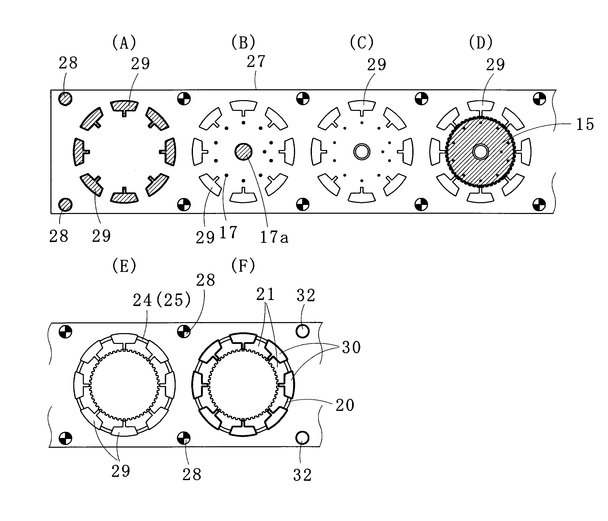
The present invention provides a method for manufacturing a laminated core for a stepping motor that can efficiently produce stator core sheets with high yield and minimal distortion. The method involves punching out rotor and stator core sheets from a thin strip material and laminating them inside a die. To form the magnetic pole pieces, the method includes preparatory slots, smaller than finishing slots, which are blanked to prevent distortion caused by coining. The invention aims to improve caulking accuracy, dimensional accuracy, and magnetic properties of the laminated core.

Problems solved by technology

What is worse, the die device may be damaged due to clogging of scraps including the metal clippings.
If magnetic pole pieces, specifically magnetic pole teeth located radially inside the stator core sheet, cannot be blanked in a desired shape, the rotor core sheet and the stator core sheet have to be blanked using the different die devices, which results in a low material yield and a high cost.

Method used


Image

  • Method for manufacturing laminated core
  • Method for manufacturing laminated core
  • Method for manufacturing laminated core

Examples


Embodiment Construction

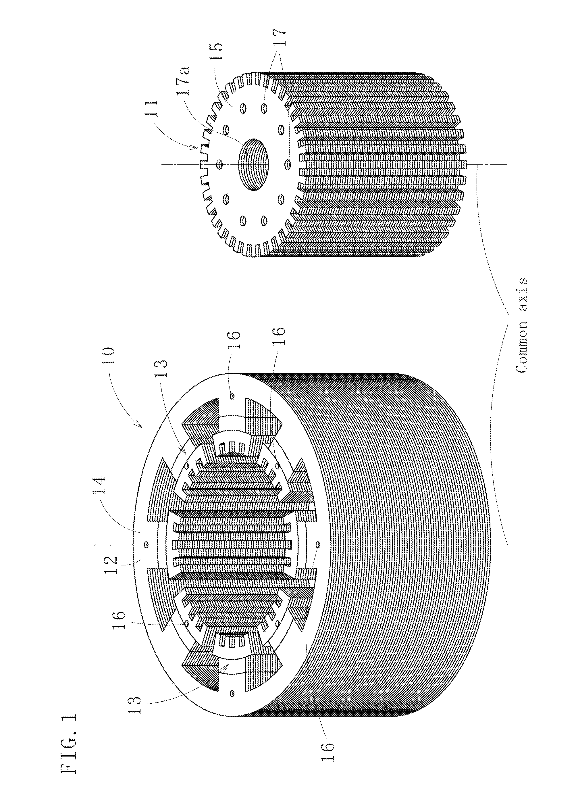
[0036]FIG. 1 shows a stator core 10 and a rotor core 11, manufactured by a method for manufacturing a laminated core according to one embodiment of the present invention. The stator core 10 and the rotor core 11 are used for a stepping motor. The stator core 10 includes a yoke section 12 having an annular shape when viewed from the top and a plurality of magnetic pole sections 13 provided inside the yoke section 12. The stator core 10 and the rotor core 11 are respectively formed by caulking (interlocking) and laminating stator core sheets 14 and rotor core sheets 15, and both of the core sheets 14, 15 are made of a magnetic steel sheet. Here, reference signs 16, 17 indicate caulking (interlocking) portions, and a reference sign 17a indicates a shaft hole. The caulking portions 16, 17 are well-known half-press caulking (half-hollow rivet) or V-shaped caulking.

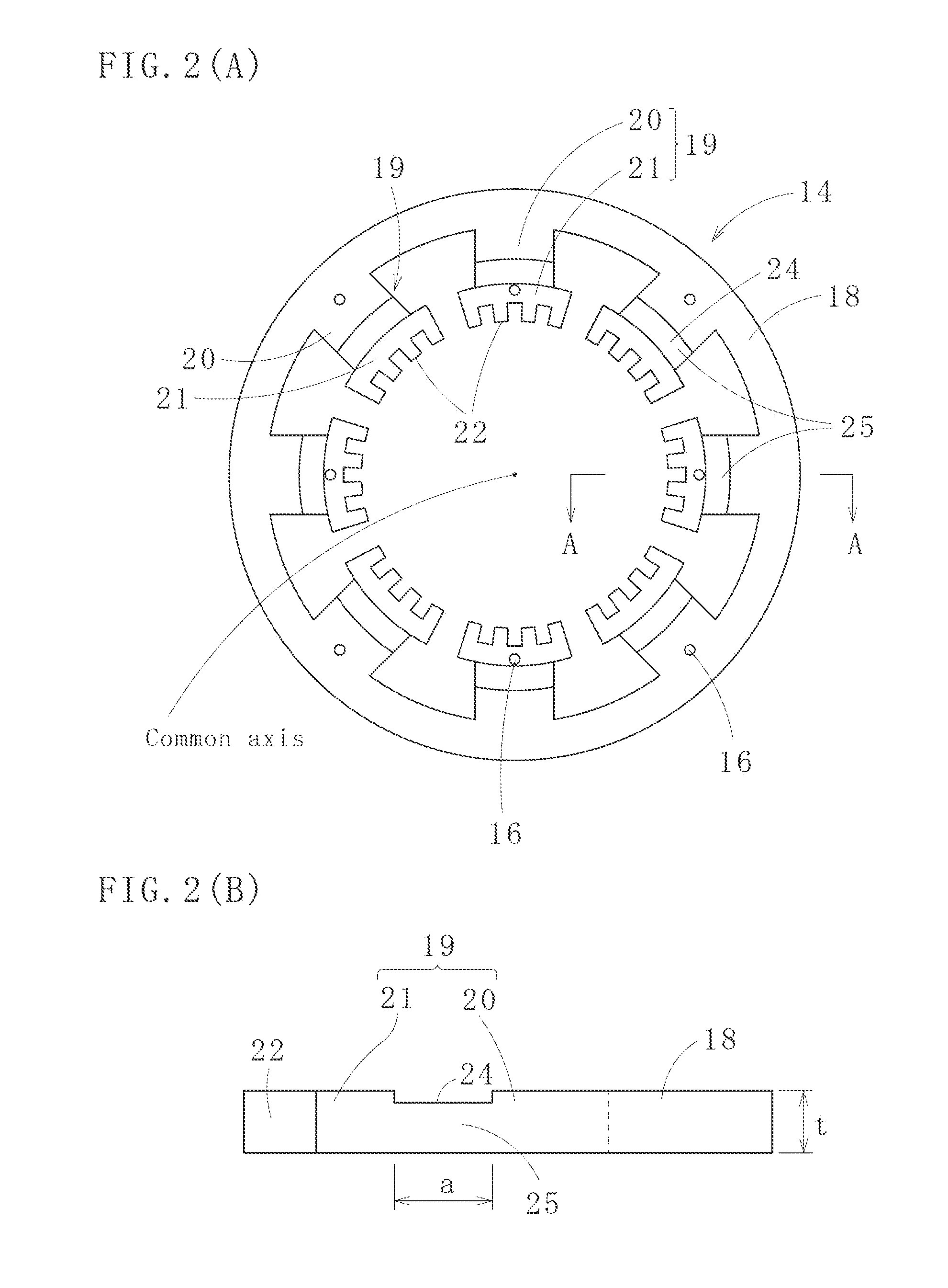
[0037]As shown in FIGS. 2 (A) and 2 (B), the stator core sheet 14 includes a ring-shaped yoke piece 18 and a plurality of (ei...


PUM

PropertyMeasurementUnit
radial lengthaaaaaaaaaa
elongationaaaaaaaaaa

Abstract

A method for manufacturing a laminated core includes (1) blanking a rotor core sheet 15 and a stator core sheet 14 from a thin strip material 27 and (2) laminating the stator core sheet 14 inside a die. The stator core sheet 14 includes a ring-shaped yoke piece 18 and plural magnetic pole pieces 19 integrally connecting to a radially inside of the yoke piece 18. Each of the magnetic pole pieces 19 includes a magnetic pole shaft piece 20 and a magnetic pole tooth piece 21. The magnetic pole pieces 19 are formed by blanking preparatory slots 29; coining a part or a whole of the magnetic pole shaft pieces 20 to elongate the same in a radially inward direction; and thereafter, blanking the finishing slots 30 and shaping the magnetic pole tooth pieces 21.

Description

TECHNICAL FIELD[0001]The present invention relates to a method for manufacturing a laminated core which is applicable to, for example, a stepping motor. The method is highly productive and operable to produce stator core sheets from a thin strip material (magnetic steel sheet) with a high yield.BACKGROUND ART[0002]Conventionally, a laminated core for a stepping motor has a very small air gap between a rotor and a stator. When a rotor core sheet and a stator core sheet, respectively used for the rotor and the stator, are produced from one thin strip material, small metal clippings are formed in narrow gaps therebetween. The metal clippings may be broken during a punching operation and not drop into a downside of a die, a part of a die device, thereby requiring the punching operation again. What is worse, the die device may be damaged due to clogging of scraps including the metal clippings.[0003]If magnetic pole pieces, specifically magnetic pole teeth located radially inside the stat...

Claims


Application Information

Patent Timeline
Patent Type & Authority Patents(United States)
IPC IPC(8): H02K15/02
CPCH02K1/146H02K15/022Y10T29/5137Y10T29/49078Y10T29/49012Y10T29/53143Y10T29/49009
Inventor HASHIMOTO, AKIHIRO
Owner MITSUI HIGH TEC INC
Learn More