
Image processing apparatus, image processing method, and storage medium

a technology of image processing apparatus and image processing method, which is applied in the direction of color television details, television system details, television systems, etc., can solve the problems of difficult to correctly specify adjacent images, difficult to obtain satisfactory connection results, and difficult to connect captured images

Active Publication Date: 2012-10-02
CANON KK
View PDF10 Cites 7 Cited by
  • Summary
  • Abstract
  • Description
  • Claims
  • Application Information

AI Technical Summary

Benefits of technology

[0012]According to the present invention having the above-mentioned configuration, a plurality of captured images obtained by divided capture of an object can be appropriately connected to each other by appropriately estimating the camera position in image capture for each of the plurality of images, and performing their lens aberration correction and perspective correction corresponding to this camera position.

Problems solved by technology

A most serious challenge in such an image capturing system is an image connection process of the captured images.
However, if the object is captured as images that have uniform regions or are partially even and therefore have little difference between them, it is very difficult to correctly specify adjacent images such that a satisfactory connection result can not be obtained with this technique.
Also, because different errors are generated in respective captured images due to the influence of, for example, the lens aberration and the object perspective, if a simple comparison is insufficient to obtain correct corresponding points, no appropriate connection result may be obtained either.
For this reason, images including fine repetitive patterns, such as a mounting of a hanging scroll, may not be able to be correctly connected to each other.
Hence, a method of calculating the relative position between images, as in Japanese Patent Laid-Open No. 07-174538 mentioned above, is insufficient to appropriately correct this error, so the object distance for each image or the camera position in image capture must be correctly estimated.
Also, appropriate perspective correction cannot be performed by simply adopting coordinate transformation such as rotation / translation for the captured images.
Furthermore, when vignetting correction is adopted in accordance with camera settings in image capture, the amount of noise increases in a direction away from the image center.
Upon adopting such correction, even the method of using a second-order derivative, mentioned above, is insufficient to eliminate the influence of the luminance.

Method used


Image

  • Image processing apparatus, image processing method, and storage medium
  • Image processing apparatus, image processing method, and storage medium
  • Image processing apparatus, image processing method, and storage medium

Examples


first embodiment

[0071]The camera position can be updated in step S1003 using, for example, a method of changing, in ±100 steps, parameter values which define the camera position for each captured image, as in the In this case, evaluation values for all captured images are calculated in each step for each captured image. It is also possible to designate camera position search conditions in advance. That is, instead of updating all parameter values for all captured images in a round-robin fashion, parameter values to be updated are determined as search conditions in advance. In this case, evaluation values for all captured images are calculated for only a parameter value designated as a search condition.

[0072]In step S1006, an overall evaluation value is calculated by calculating the average of the calculated evaluation values for respective captured images. In step S1007, it is determined whether the overall evaluation value is a minimum up to the current process. If the overall evaluation value is...

second embodiment

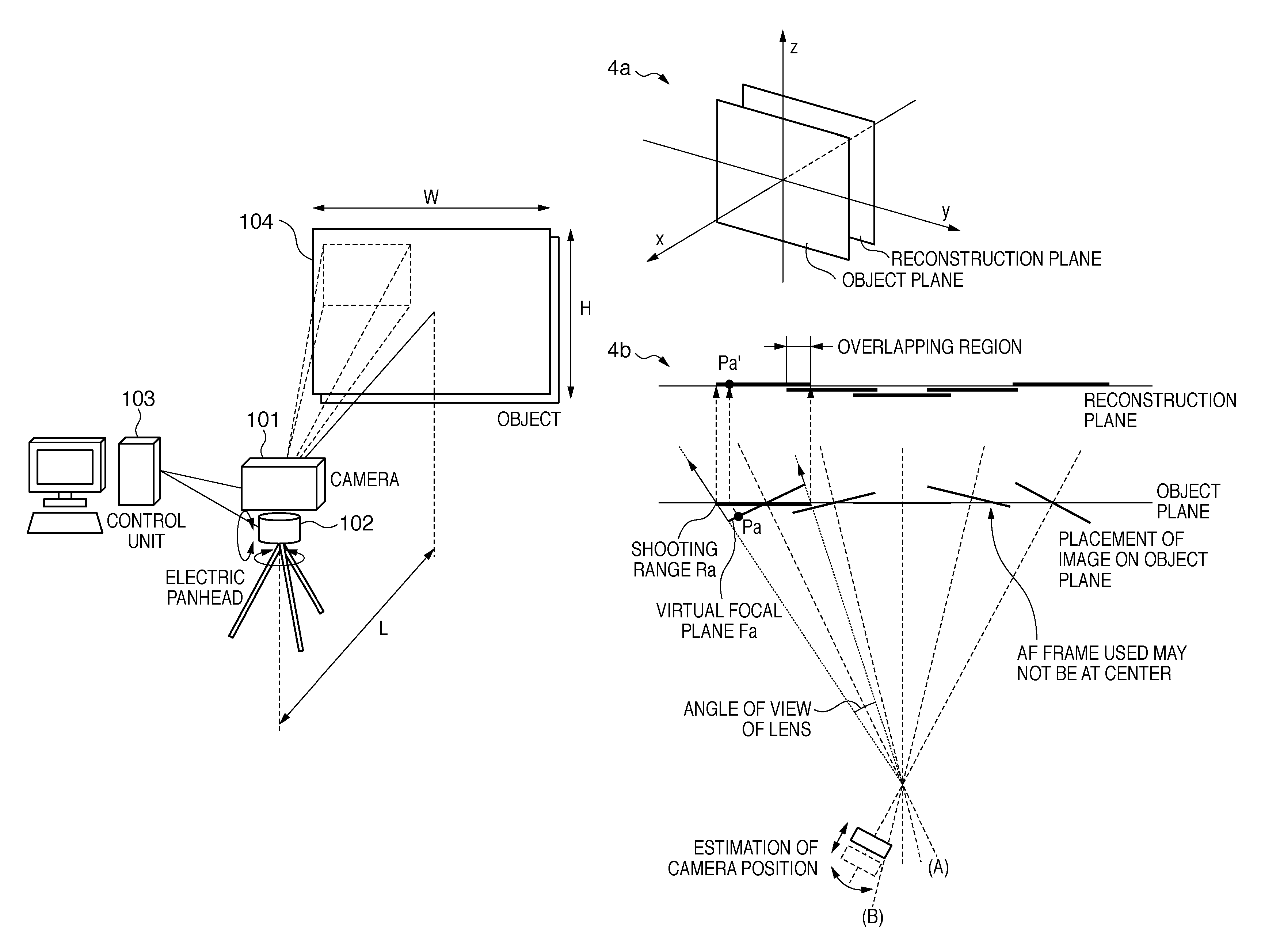
[0073]In step S1009, it is determined whether to end the camera position estimation process. In the second embodiment, it is determined whether to end the estimation process using the fact that the overall evaluation value is smaller than a predetermined value as an end condition. If the end condition is not satisfied, the process returns to step S1003, in which the estimation process continues. If the end condition is satisfied, in step S1010 each captured image is projected onto the reconstruction plane in accordance with its optimal camera position to obtain a connection result, and the process ends.

[0074]As has been described above, according to the second embodiment, an optimal image connection result can be obtained while preventing the camera position from resulting in a local minimum, by means of setting an overall evaluation value for all captured images obtained by divided capture, and performing a camera estimation process.

[0075]

[0076]The third embodiment according to the...

third embodiment

[0078]To cope with this situation, in the third embodiment, errors are divided into global errors common to the entire group of captured images, and local errors which differ for each captured image. More specifically, a first parameter related to a global error is estimated by selecting some overlapping regions, this error is corrected for all images, and thereafter a second parameter related to a local error is estimated, and a correction process is performed for each image. With such a process, the number of combinations of different errors is decreased, thereby making it possible to reduce the amount of calculation. For example, assume that four estimation parameters are set for a certain overlapping region, about 1.6 billion evaluation value calculation processes are necessary to obtain an optimal solution in a round-robin fashion. However, when only one of these parameters is separately calculated as a global error, only 8 million evaluation value calculation processes need to...


PUM


Abstract

The invention provides an image processing apparatus comprising: an acquisition unit configured to acquire a plurality of captured images captured by an image capturing apparatus; a determination unit configured to determine position information of the image capturing apparatus for each of the plurality of captured images so that an evaluation value becomes smaller; and a connecting unit configured to connect the plurality of captured images projected onto a reconstruction plane using the determined position information of the image capturing apparatus, wherein the determination unit comprises a calculation unit configured to project each of the plurality of captured images onto the reconstruction plane based on the set position information and to calculate, as the evaluation value, an image difference between the projected images in a overlapping region between the projected images.

Description

BACKGROUND OF THE INVENTION[0001]1. Field of the Invention[0002]The present invention relates to an image processing apparatus and image processing method that capture an object that is larger than a view of an image capturing apparatus by a plurality of times to obtain a captured image of the entire object.[0003]2. Description of the Related Art[0004]An electric panhead has been conventionally known as a device that is attached between a tripod and a camera and used to electromotively rotate the camera, which is set in its upper portion, through a predetermined angle. In recent years, a system which captures a plurality of images while changing the orientation of the image capturing camera by driving the electric panhead, and connects the captured images to each other, thereby generating an image (for example, a panoramic image) with a very large number of pixels is attracting a great deal of attention. A most serious challenge in such an image capturing system is an image connecti...

Claims


Application Information

Patent Timeline
Patent Type & Authority Patents(United States)
IPC IPC(8): H04N5/225H04N7/00H04N5/228
CPCH04N5/232H04N7/185H04N5/23203H04N23/66H04N23/695
Inventor KOTANI, TAKUYA
Owner CANON KK
Learn More