
Non-pneumatic tire

a non-pneumatic tire technology, applied in the field of non-pneumatic tires, can solve the problems of difficult to completely prevent buckling, heavy weight of non-pneumatic tires, tire destruction, etc., and achieve the effect of preventing buckling of the cylindrical outer member

Inactive Publication Date: 2012-10-02
THE YOKOHAMA RUBBER CO LTD
View PDF27 Cites 29 Cited by
  • Summary
  • Abstract
  • Description
  • Claims
  • Application Information

AI Technical Summary

Benefits of technology

The present invention provides a non-pneumatic tire with a spoke structure that prevents buckling without adding weight. The spokes are arranged intermittently in the tire circumferential direction and have air-containing spaces between them. These spaces help disperse the load and prevent buckling of the tire when it is subjected to a radial load. The air pressure in the spaces is set higher than the atmospheric pressure, and the spokes can be divided into zones to further enhance the load-dispersing effect. Overall, this design prevents buckling without adding weight or increasing the number of spokes.

Problems solved by technology

However, the conventional non-pneumatic tires are heavy in weight, and lack a shock absorbing characteristic, and therefore, have not been adopted for application to passenger vehicles, in which ride comfort performance is considered important.
If this buckling phenomenon occurs repeatedly at every rotation of the tire, not only vibration and abnormal wear in a tread ring are caused, but it eventually leads to destruction of the tire.
However, even in this non-pneumatic tire, it is difficult to completely prevent buckling in some cases such as when a large load acts upon the tire.
Moreover, if a countermeasure against the buckling, such as increasing the number of spokes, or thickening a tread, is taken, it leads to weight increase thereof.
For these reasons, this non-pneumatic tire is not necessarily considered as a satisfactory countermeasure.

Method used


Image

  • Non-pneumatic tire
  • Non-pneumatic tire
  • Non-pneumatic tire

Examples


Embodiment Construction

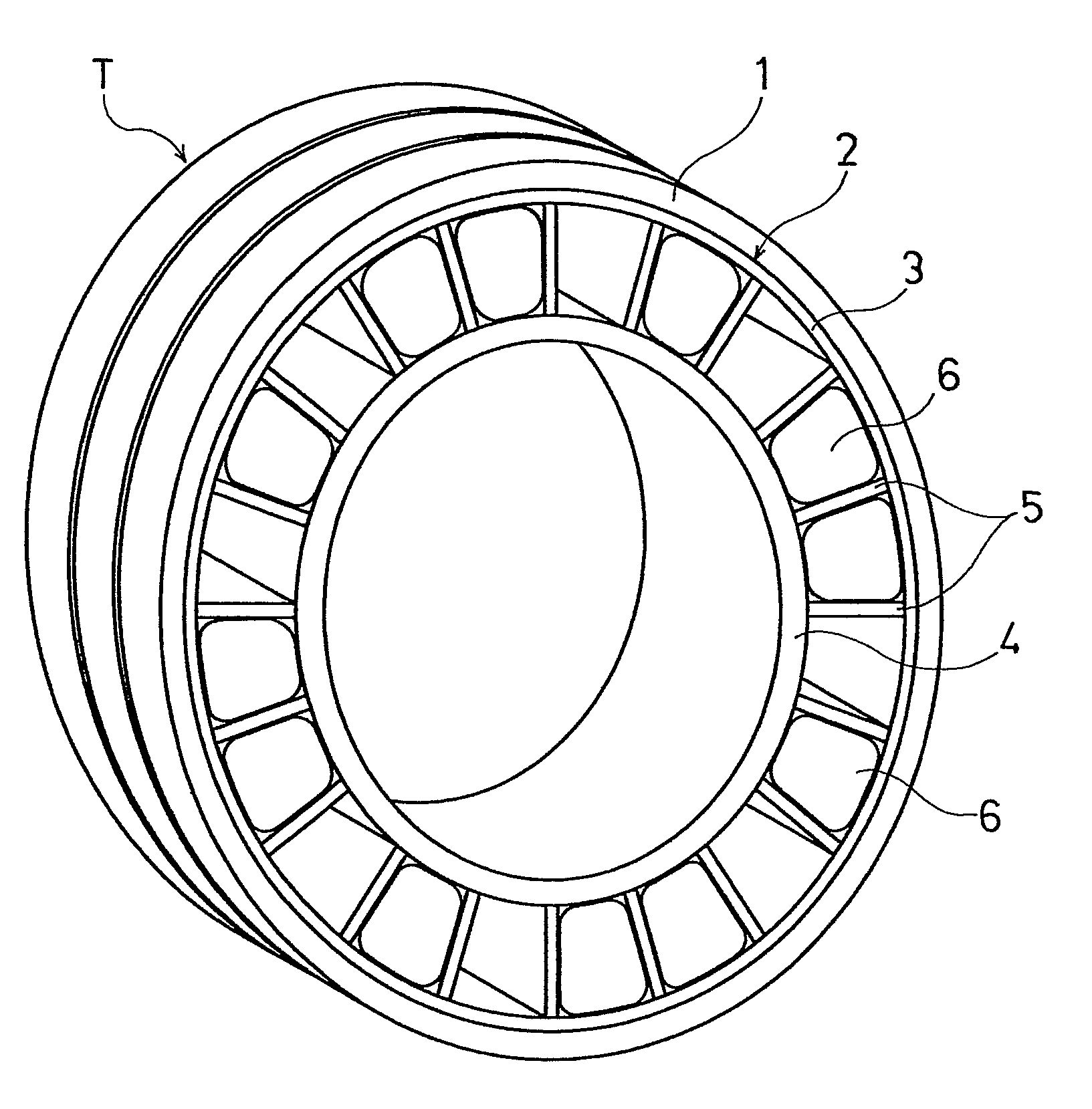
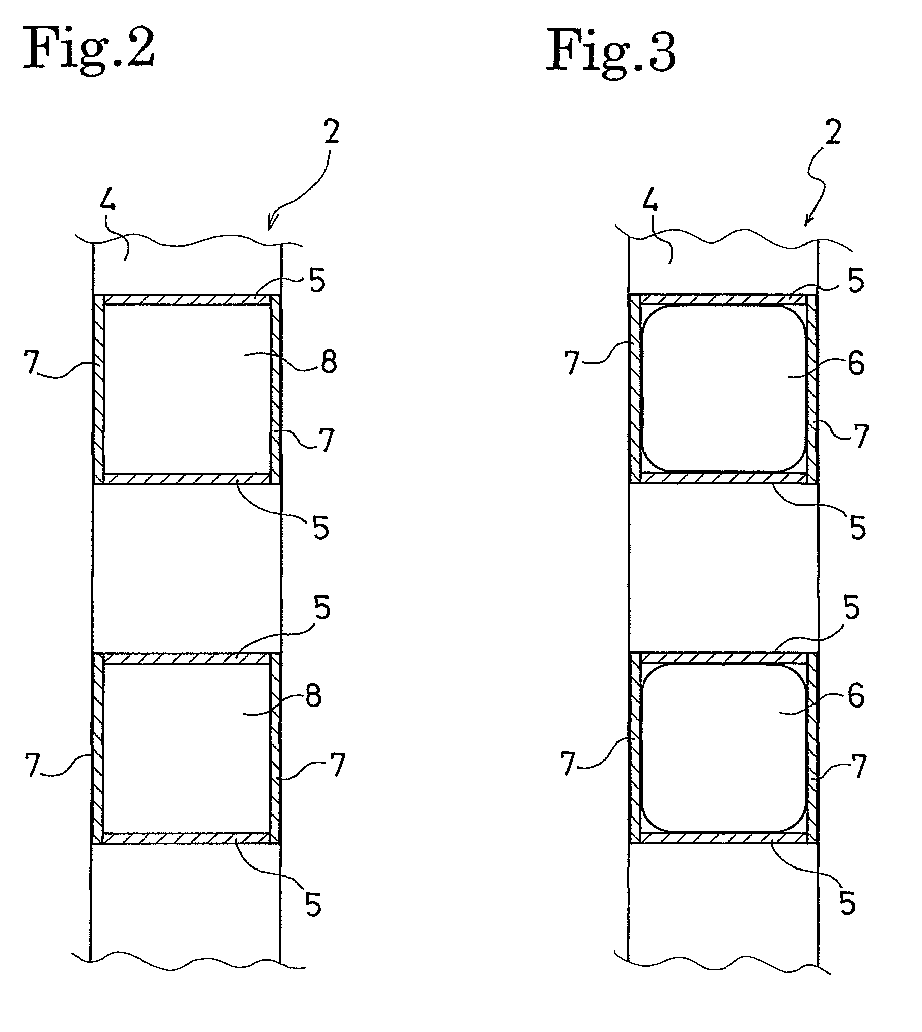
[0023]As shown in FIG. 1, a non-pneumatic tire of the present invention includes a tread ring 1 and a spoke structure 2 joined to an inner peripheral side of the tread ring, and the spoke structure 2 has a large number of spokes 5 arranged radially between an annular cylindrical outer member 3 and a cylindrical inner member 4 at intervals in the circumferential direction, the spokes 5 coupling the cylindrical outer member 3 and the cylindrical inner member 4 together.

[0024]In this spoke structure 2, at least some of a plurality of spaces each formed between adjacent two, in the tire circumferential direction, of those spokes 5 each have an air-containing structure. In an illustrated example, this air-containing structure is obtained by press fitting, into a space between the two spokes 5, 5, an elastic bag body 6 having air sealed therein. There is no particular limitation as to the elastic bag body having air sealed therein, and, for example, a rubber bag body, a rubber ball, an ur...


PUM


Abstract

Provided is a non-pneumatic tire in which buckling can be prevented without a weight increase, the non-pneumatic tire including a spoke structure. The spoke structure is obtained by circumferentially arranging spokes intermittently at intervals and coupling together annular cylindrical outer member and cylindrical inner. The spoke structure is joined to an inner peripheral side of a tread ring. At least some of a plurality of spaces formed between two spokes adjacent to each other in the tire circumferential direction have an air-containing structure.

Description

FIELD OF THE INVENTION[0001]The present invention relates to a non-pneumatic tire. More specifically, the present invention relates to a non-pneumatic tire including a spoke structure and being capable of preventing buckling from occurring without an associated increase in weight.DESCRIPTION OF THE PRIOR ART[0002]Conventionally, as non-pneumatic tires, a solid tire, a cushion tire and the like having a solid rubber structure, have been mainly used for industrial vehicles. However, the conventional non-pneumatic tires are heavy in weight, and lack a shock absorbing characteristic, and therefore, have not been adopted for application to passenger vehicles, in which ride comfort performance is considered important.[0003]In order to improve ride comfort performance of the above described non-pneumatic tires, and thereby to make them adoptable for application to passenger vehicles, there has been proposed a non-pneumatic tire T, as shown in FIG. 9, achieving weight reduction and the shoc...

Claims


Application Information

Patent Timeline
Patent Type & Authority Patents(United States)
IPC IPC(8): B60B9/00B60C5/00
CPCB60C7/12B60C17/061Y10T152/10054B60C2007/107B60C7/107
Inventor HANADA, RYOJISETO, HIDEKIHASHIMURA, YOSHIAKIMATSUDA, JUNKITAZAKI, TSUYOSHIKURAMOCHI, IZUMIENDO, KENICHIROU
Owner THE YOKOHAMA RUBBER CO LTD
Learn More