Wind turbine rotor blade

a technology of wind turbines and rotor blades, which is applied in the direction of machines/engines, sustainable manufacturing/processing, and final product manufacturing, etc., can solve the problems of difficulty in integral manufacturing, difficulty in securing roads and trucks, and difficulty in conveyancing, so as to achieve the effect of increasing weight, increasing strength, and increasing siz

Active Publication Date: 2012-04-26
MITSUBISHI HEAVY IND LTD
View PDF3 Cites 15 Cited by
  • Summary
  • Abstract
  • Description
  • Claims
  • Application Information

AI Technical Summary

Benefits of technology

[0029]According to the wind turbine rotor blade according to the present invention, since the beams, which are the main strength members of the separated blades, are coupled to each other by the metallic coupling members, an advantageous effect is produced that a sufficient strength in the coupling portion can be secured without significant increase in weight even though the blade is increased in size.

Problems solved by technology

When the wind turbine rotor blade is increased in size as described above, various difficulties, such as a difficulty in integral manufacture and a difficulty in conveyance along with difficulties in securing roads and trucks, etc., occur.

Method used


Image

  • Wind turbine rotor blade
  • Wind turbine rotor blade
  • Wind turbine rotor blade

Examples


Embodiment Construction

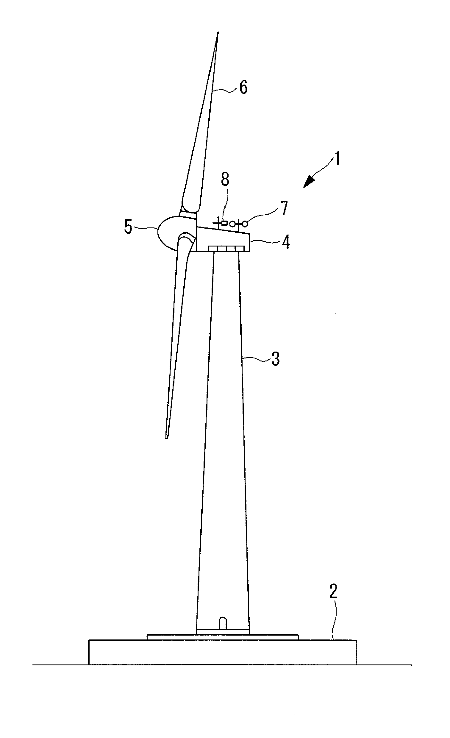
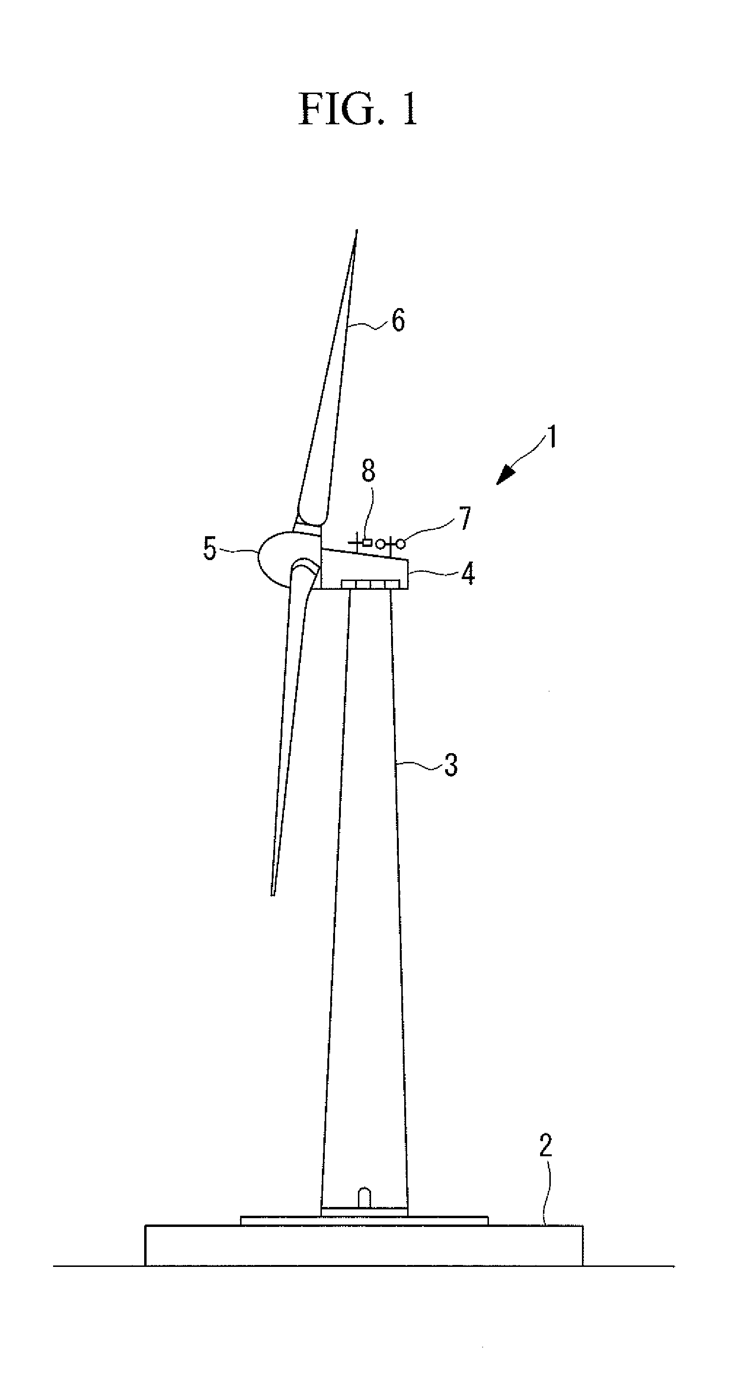
[0043]Hereinafter, a wind turbine rotor blade according to one embodiment of the present invention will be described with reference to FIGS. 1 to 10.

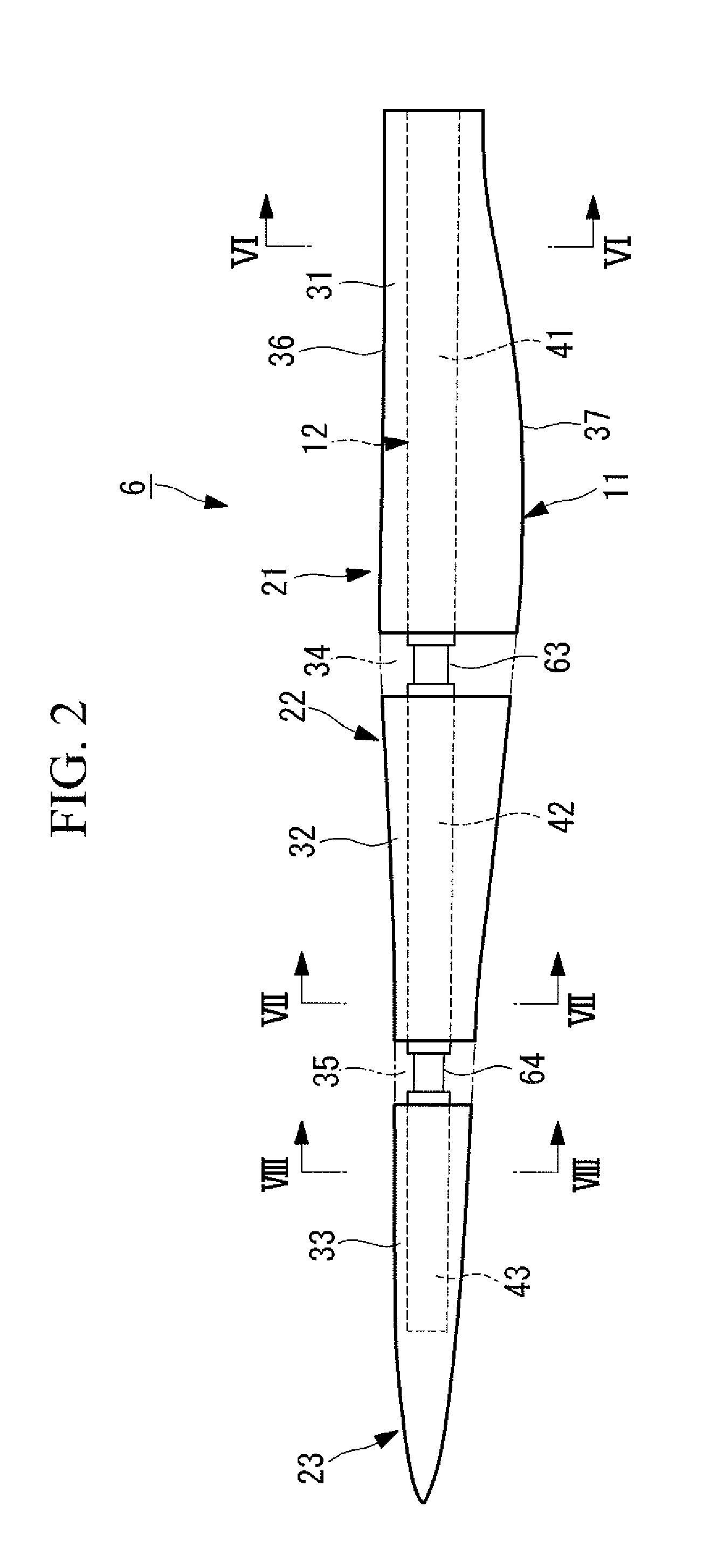
[0044]FIG. 1 is a side view showing a wind turbine for wind power generation including a wind turbine rotor blade according to the present invention; FIG. 2 is a plan view showing a state in the middle of assembly of the wind turbine rotor blade according to the embodiment; FIG. 3 is an enlarged cross-sectional view of a main part of FIG. 2; FIG. 4 is a cross-sectional view showing a state after completion of assembly of the wind turbine rotor blade according to the embodiment; FIG. 5 is a cross-sectional view showing a state after completion of assembly of a wind turbine rotor blade according to an other embodiment; FIG. 6 is an arrow cross-sectional view taken along a line VI-VI of FIG. 2; FIG. 7 is an arrow cross-sectional view taken along a line VII-VII of FIG. 2; FIG. 8 is an arrow cross-sectional view taken along a line VIII-VIII ...


PUM


Abstract

Provided is a wind turbine rotor blade that can secure a sufficient strength in a coupling portion without significant increase in weight even though a blade is increased in size because beams, which are main strength members of the separated blades, are coupled to each other by metallic coupling members. A wind turbine rotor blade including: a skin that forms a long hollow shape; and a beam that is vertically passed in a longitudinal direction to reinforce the skin from inside, wherein the beam is separated into at least two portions in the longitudinal direction, and ends of the adjacent beams are coupled to each other through a metallic coupling member having: a first flange portion opposed to the one end; a second flange portion opposed to the other end; and a connecting portion that connects these first flange portion and second flange portion, and the skin is separated into a coupling portion skin arranged at a position corresponding to the coupling member, and a main body skin arranged at a position corresponding to the beam.

Description

TECHNICAL FIELD[0001]The present invention relates to a wind turbine rotor blade that constitutes a wind turbine for wind power generation.BACKGROUND ART[0002]In recent years, wind turbines for wind power generation have increased in size to achieve improvement in power generation efficiency and to increase of the amount of power generation. Along with the increase in size of wind turbines for wind power generation, wind turbine rotor blades have also increased in size, to have for example, a blade length of not less than 40 meters.[0003]When the wind turbine rotor blade is increased in size as described above, various difficulties, such as a difficulty in integral manufacture and a difficulty in conveyance along with difficulties in securing roads and trucks, etc., occur.[0004]In order to solve these difficulties, there has been proposed a wind turbine rotor blade that is separated in a longitudinal direction as disclosed in Patent Literature 1.{Citation List}{Patent Literature}{PT...

Claims


Application Information

Patent Timeline
IPC IPC(8): F03D3/06
CPCF03D1/001F03D1/0675Y02E10/728Y02E10/721F05B2230/601F05B2260/301F05B2230/60F03D80/30F05B2240/302F03D13/10Y02E10/72Y02P70/50F03D1/06
Inventor KAWASETSU, NOZOMUSHINDO, KENTAROKUROIWA, TAKAOHORI, SHINICHI
Owner MITSUBISHI HEAVY IND LTD
Why Eureka
Try Eureka