
Miniaturized GPS/MEMS IMU integrated board

a technology of imu and integrated board, applied in the field of machine vision systems, can solve problems such as machine vision systems, and achieve the effects of smooth preprocessing operation, improved segmentation results, and convenient computation

Active Publication Date: 2012-09-25
AMERICAN GNC
View PDF6 Cites 24 Cited by
  • Summary
  • Abstract
  • Description
  • Claims
  • Application Information

AI Technical Summary

Benefits of technology

"The present invention provides a method and system for positioning and integrating electro-optic image sensors in a navigation system. The invention uses feature matching and corner detection to accurately position and identify objects in real-time. The system combines the use of GPS, inertial sensors, and laser rangers to provide reliable and precise positioning information. The invention also includes a method for detecting and matching features in images, as well as a method for identifying objects based on their shape and size. Overall, the invention improves the efficiency and reliability of machine vision systems for autonomous navigation and contingency operations."

Problems solved by technology

There are two difficult problems for machine vision systems.

Method used


Image

  • Miniaturized GPS/MEMS IMU integrated board
  • Miniaturized GPS/MEMS IMU integrated board
  • Miniaturized GPS/MEMS IMU integrated board

Examples


Embodiment Construction

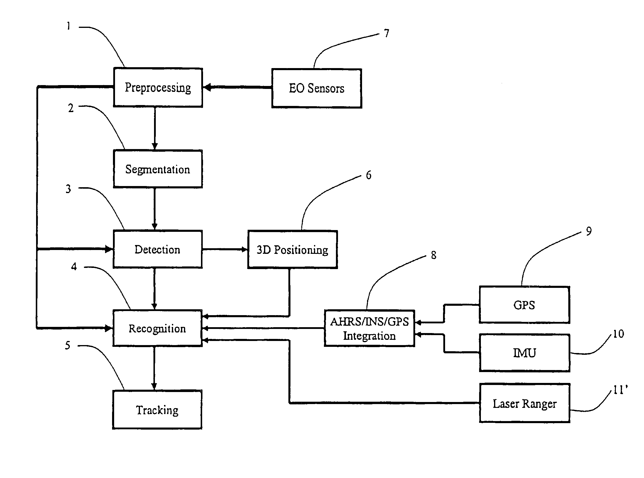
[0054]Generally, IMU / GPS integration can output the position, attitude and azimuth of the vehicle itself. A laser ranger measures the distance between the object and vehicle. Electro-optic image sensors derive the 3D environment in the field of view. The traditional electro-optic sensor image processing is time consuming and unreliable.

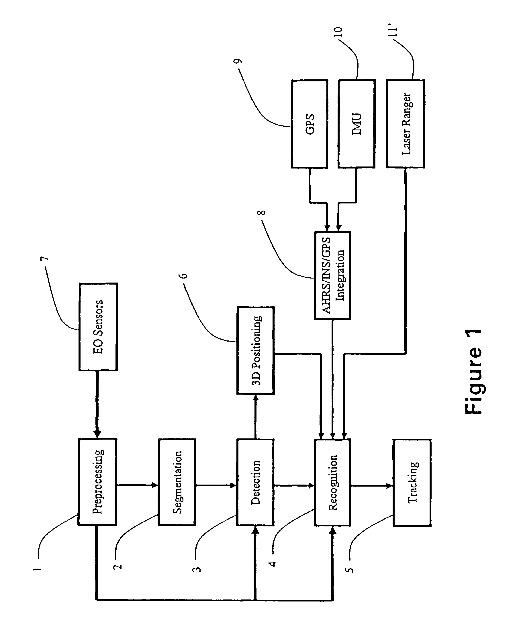
[0055]Referring to FIG. 1, the electro-optic sensor image processing comprises a preprocessing module 1, a segmentation module 2, a detection module 3, a recognition module 4, a 3D-positioning module 5, a tracking module 6, EO sensors 7, an AHRS / INS / GPS Integration module 8, a GPS receiver 9, a MEMS IMU 10, and a laser ranger 11.

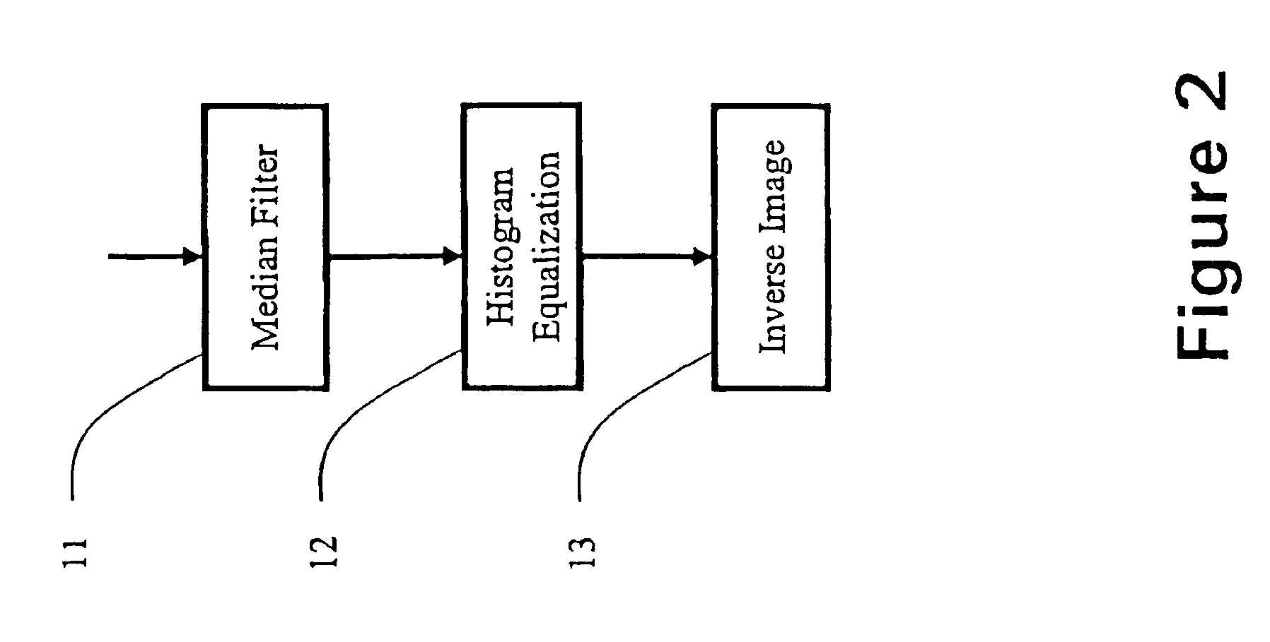
[0056]Referring to FIG. 2, the preprocessing module 1 comprises a Median Filter module 11, a Histogram Equalization module 12 and an Inverse Image module 13.

[0057]Referring to FIG. 3, the segmentation module 2 comprises a Threshold Black / White module 21, a Suppress Black module 22, a Suppress White module 23, and a Sobel Filte...


PUM


Abstract

This invention documents the efforts on the research and development of a miniaturized GPS / MEMS IMU integrated navigation system. A miniaturized GPS / MEMS IMU integrated navigation system is presented; Laser Dynamic Range Imager (LDRI) based alignment algorithm for space applications is discussed. Two navigation cameras are also included to measure the range and range rate which can be integrated into the GPS / MEMS IMU system to enhance the navigation solution.

Description

CROSS REFERENCE OF RELATED APPLICATION[0001]This is a non-provisional application of a provisional application having application No. 60 / 880,345 and filing date of Jan. 12, 2007, and is a Continuation-In-Part application of application Ser. No. 10 / 912,401 filed on Aug. 4, 2004 now U.S. Pat. No. 7,376,262.[0002]This invention was made with Government support under contract NAS9-99024 awarded by NASA. The Government has certain rights in the invention.BACKGROUND OF THE PRESENT INVENTION[0003]1. Field of Invention[0004]The present invention relates generally to machine vision systems, and more particularly to object positioning, which employs electro-optic (EO) image sensors enhanced with integrated laser ranger, global positioning system / inertial measurement unit, and integrates this data to get reliable and real time object position.[0005]2. Description of Related Arts[0006]There are two difficult problems for machine vision systems. One is image processing speed, another is the reli...

Claims


Application Information

Patent Timeline
Patent Type & Authority Patents(United States)
IPC IPC(8): G06K9/00G06K9/62G01C21/00G06K9/66
CPCG06K9/3216G06K9/6293G06T7/0044G06T7/0085G06T2207/20164G06T7/74G06T7/13G06V10/245G06V10/811G06F18/256
Inventor LIN, CHING-FANG
Owner AMERICAN GNC
Learn More