Composite sheet and absorbent article using the composite sheet
a composite sheet and absorbent material technology, applied in the field of composite sheets, can solve problems such as difficulty in suppressing rewetting, and achieve the effect of superior liquid drawing ability (spot property) and superior ability to suppress backs
- Summary
- Abstract
- Description
- Claims
- Application Information
AI Technical Summary
Benefits of technology
Problems solved by technology
Method used
Image
Examples
first embodiment
2.1. First Embodiment
2.1.1. Overall Configuration
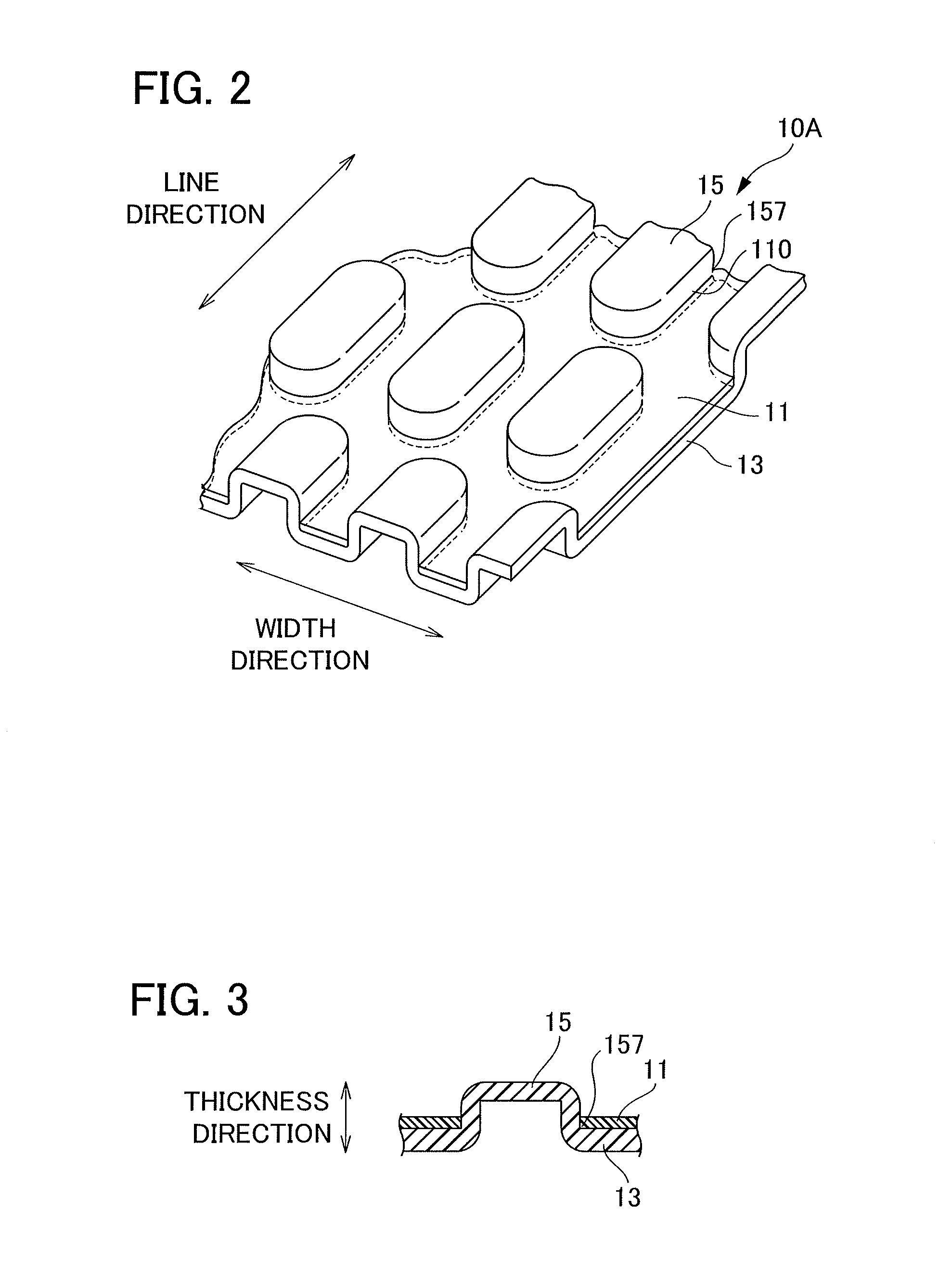
[0067]A composite sheet 10A according to a first embodiment is described hereinafter with reference to FIGS. 2 and 3. As shown in FIG. 2, the composite sheet 10A includes a film sheet 11 on which a plurality of openings 110 is formed, and a fiber aggregate 13 that is disposed to be layered on one side of the film sheet 11. A portion of the fiber aggregate 13 has a plurality of projecting regions 15 that project to another side of the film sheet 11 through the plurality of openings 110. A film sheet on which the openings 110 are formed in advance can be used as the film sheet 11 for the composite sheet.
[0068]The projecting regions 15 on the composite sheet 10 can have a height (length in a thickness direction) of 0.3 to 5.0 mm, and more particularly of 0.5 to 2.0 mm. In addition, the projecting regions 15 can have a length in a planar direction (width or diameter) of 0.5 to 10 mm, and more particularly of 1.0 to 5.0 mm. Furthermore, a ...
second embodiment
2.2. Second Embodiment
2.2.1. Overall Configuration
[0092]A composite sheet 10B according to a second embodiment is described hereinafter with reference to FIGS. 4 and 5. Unlike the composite sheet 10A according to the first embodiment, a film sheet 11, on which openings 110 are not formed in advance, is used in the composite sheet 10B according to the present embodiment. In other words, in the present embodiment, projecting portions 15 are formed while forming slits by splitting portions of the film sheet 11, in the projecting region forming step.
[0093]More specifically, as shown in FIG. 4 or 5, the composite sheet 10B according to the present embodiment is a composite sheet that includes the film sheet 11 and the fiber aggregate 13, the film sheet 11 having a plurality of slits 120 formed therein, and the fiber aggregate 13 being disposed to be layered on one side of the film sheet 11 and having a plurality of projecting regions 15 projecting toward another side of the film sheet 11...
third embodiment
2.3. Third Embodiment
2.3.1. Overall Configuration
[0110]A composite sheet 10C according to a third embodiment is described hereinafter with reference to FIGS. 6 to 9. The composite sheet 10C according to the present embodiment is a composite sheet in which the projecting regions 15 are formed at smaller intervals in the width direction than in the composite sheet 10B according to the second embodiment.
[0111]More specifically, as shown in FIGS. 6 to 9, the composite sheet 10C according to the present embodiment is a composite sheet that includes the film sheet 11 and the fiber aggregate 13, the film sheet 11 having a plurality of slits 120 formed therein, and the fiber aggregate 13 being disposed to be layered on one side of the film sheet 11 and having a plurality of projecting regions 15 projecting toward another side of the film sheet 11, which are a part of the fiber aggregate 13 passing through the plurality of slits 120.
[0112]The film sheet 11 in the composite sheet 10C is dispo...
PUM
| Property | Measurement | Unit |
|---|---|---|
| diameter | aaaaa | aaaaa |
| diameter | aaaaa | aaaaa |
| diameter | aaaaa | aaaaa |
Abstract
Description
Claims
Application Information
 - R&D
- Intellectual Property
- Life Sciences
- Materials
- Tech Scout
- Unparalleled Data Quality
- Higher Quality Content
- 60% Fewer Hallucinations
Browse by: Latest US Patents, China's latest patents, Technical Efficacy Thesaurus, Application Domain, Technology Topic, Popular Technical Reports.
© 2025 PatSnap. All rights reserved.Legal|Privacy policy|Modern Slavery Act Transparency Statement|Sitemap|About US| Contact US: help@patsnap.com


