
Impingement cooling plate for a hot gas duct of a thermal machine

a technology of hot gas duct and cooling plate, which is applied in the direction of machines/engines, stators, lighting and heating apparatus, etc., can solve the problems of adverse effect of pressure drop on the efficiency of gas turbines, and achieve the effect of reducing the transverse flow

Active Publication Date: 2012-09-25
GENERAL ELECTRIC TECH GMBH
View PDF34 Cites 5 Cited by
  • Summary
  • Abstract
  • Description
  • Claims
  • Application Information

AI Technical Summary

Benefits of technology

[0006]An aspect of the invention is the construction of a thermal machine in such a way that an improved level of efficiency is obtained through significantly improved cooling.
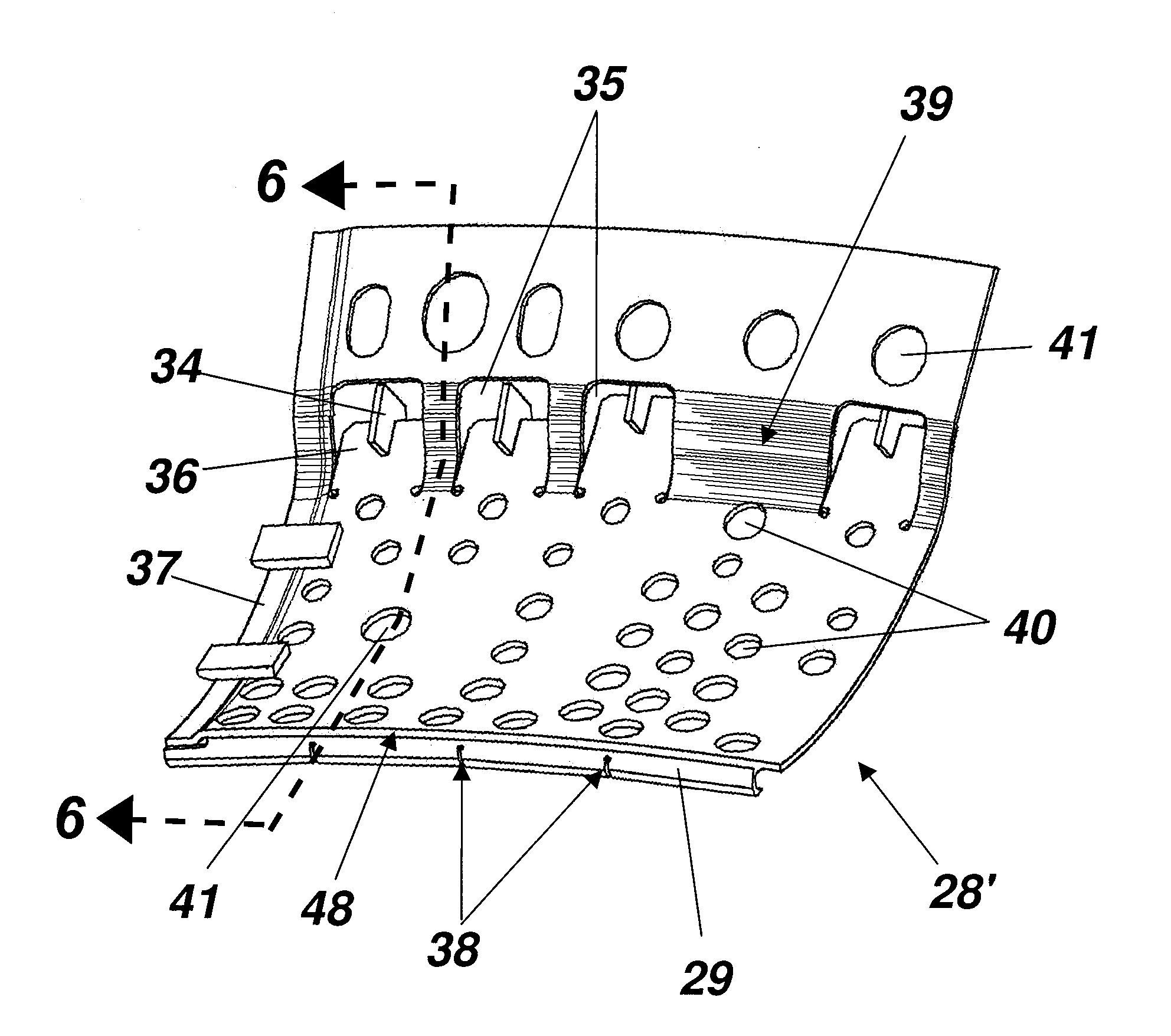
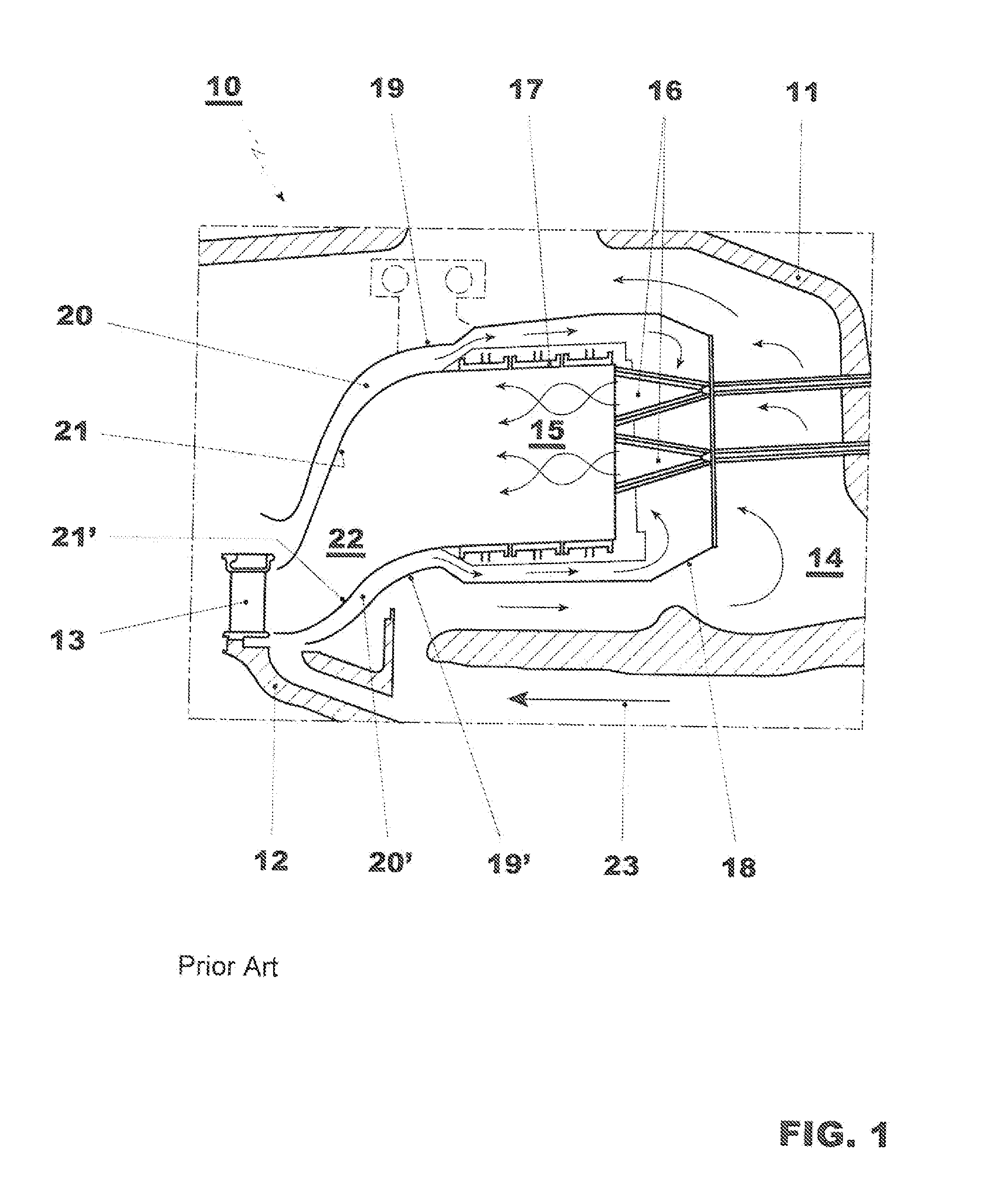
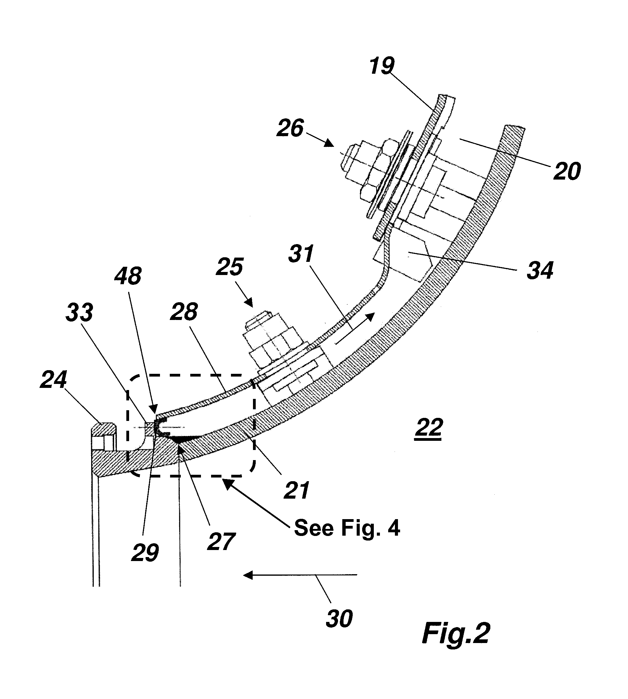
[0007]In an embodiment, the present invention provides a thermal machine including a wall defining a hot gas duct for transferring a hot gas stream and a cooling jacket disposed at a distance from the wall on an outside of the hot gas duct so as to define a cooling duct with an inlet and an outlet. The cooling duct is configured to conduct a cooling medium along an external face of the wall from the inlet to an outlet in a direction counter to a flow of hot gas in the hot gas duct. An impingement cooling plate is disposed at the inlet of the cooling duct and includes cooling baffle holes configured such that cooling medium entering the cooling duct through the cooling baffle holes flows in a direction perpendicular to the wall. The impingement cooling plate is positioned such that an inflow-side edge sealingly abuts the wall of the hot gas duct so as to reduce a transverse flow of the cooling medium through the cooling duct.

Problems solved by technology

A rise in the pressure drop has an adverse effect on the efficiency of the gas turbine.

Method used


Image

  • Impingement cooling plate for a hot gas duct of a thermal machine
  • Impingement cooling plate for a hot gas duct of a thermal machine
  • Impingement cooling plate for a hot gas duct of a thermal machine

Examples


Embodiment Construction

[0016]The present invention relates to the use of an impingement cooling plate provided at the inlet of the cooling duct, with cooling medium entering the cooling duct through the cooling baffle holes of the impingement cooling plate perpendicularly with respect to the wall of the hot gas duct so as to impinge on the wall of the hot gas duct. In order to reduce a transverse flow of the cooling medium in the cooling duct, the inflow-side edge of the impingement cooling plate abuts the wall of the hot gas duct in a seal-forming fashion.

[0017]In one embodiment of the invention the wall has an outwardly protruding shoulder at the inlet of the cooling duct, and the inflow-side edge of the impingement cooling plate abuts the shoulder in a seal-forming fashion. In this embodiment, the inflow-side edge of the impingement cooling plate loosely bears against the shoulder, and the impingement cooling plate is provided, on the inflow-side edge, with a seal which extends along the edge. The seal...


PUM


Abstract

A thermal machine including a wall defining a hot gas duct for transferring a hot gas stream and a cooling jacket disposed at a distance from the wall on an outside of the hot gas duct so as to define a cooling duct with an inlet and an outlet. The cooling duct is configured to conduct a cooling medium along an external face of the wall from the inlet to an outlet in a direction counter to a flow of hot gas in the hot gas duct. An impingement cooling plate is disposed at the inlet of the cooling duct and includes cooling baffle holes configured such that cooling medium entering the cooling duct through the cooling baffle holes flows in a direction perpendicular to the wall. The impingement cooling plate is positioned such that an inflow-side edge sealingly abuts the wall of the hot gas duct so as to reduce a transverse flow of the cooling medium through the cooling duct.

Description

CROSS-REFERENCE TO RELATED APPLICATIONS[0001]This patent application is a continuation of International Patent Application No. PCT / EP2009 / 051537 filed Feb. 11, 2009, which claims priority to Swiss Patent Application No. 00243 / 08, filed Feb. 20, 2008, both of which are incorporated by reference herein. The International Patent Application was published as WO 2009 / 103636 A1 on Aug. 27, 2009.FIELD[0002]The present invention relates to the field of thermal machines, and further relates to thermal machines including a hot gas duct and a cooling duct disposed outside the hot gas duct.BACKGROUND[0003]Gas turbines such as are offered by the applicant, for example under, inter alia, the type designation GT13E2, are operated with an annular combustion chamber. The combustion itself may occur using premixer burners (referred to below for short as burners) such as are described, for example, in EP A1 321 809 or AP A1 704 657, wherein these documents and the developments which have been made the...

Claims


Application Information

Patent Timeline
Patent Type & Authority Patents(United States)
IPC IPC(8): F02C3/00
CPCF01D9/023F01D25/26F02C6/12F23R3/005F23R3/04F23R2900/03044F05D2220/40
Inventor HAEHNLE, HARTMUTVOGEL, GREGORYJONES, RUSSELL BONDDUGGANS -ONEIL, MARIONTSCHUOR, REMIGI
Owner GENERAL ELECTRIC TECH GMBH
Learn More