Surface deformation measuring system with a retro-reflective surface treatment

a technology of surface deformation and measuring system, which is applied in the direction of instruments, measurement devices, interferometers, etc., can solve the problems of angular efficiency loss, low efficiency, and low efficiency of the host system in the treatment field

Active Publication Date: 2012-09-18
HARRIS CORP
View PDF4 Cites 13 Cited by
  • Summary
  • Abstract
  • Description
  • Claims
  • Application Information

AI Technical Summary

Problems solved by technology

Because of the diffuse nature of the reflected light from the object under test, the illumination efficiency of a HOST system is very low.
The efficiency is very low due to the fact that the diffusely reflected light scatters substantially from the object (or work piece), typically filling a large solid angle, but the receiving optics (the optics that form the image of the object under test) operates with a much smaller solid angle.
In addition, because of the angular efficiency loss, conventional HOST systems require very high power illumination lasers (greater that 100 milliwatts of optical output), or the HOST systems are restricted to work over short distances (roughly, over a distance of a meter, or less).

Method used


Image

  • Surface deformation measuring system with a retro-reflective surface treatment
  • Surface deformation measuring system with a retro-reflective surface treatment
  • Surface deformation measuring system with a retro-reflective surface treatment

Examples


Embodiment Construction

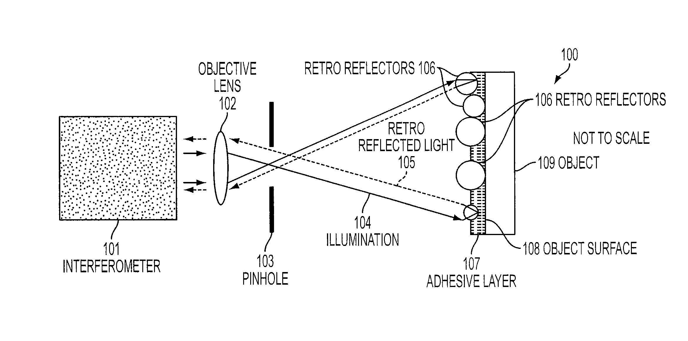
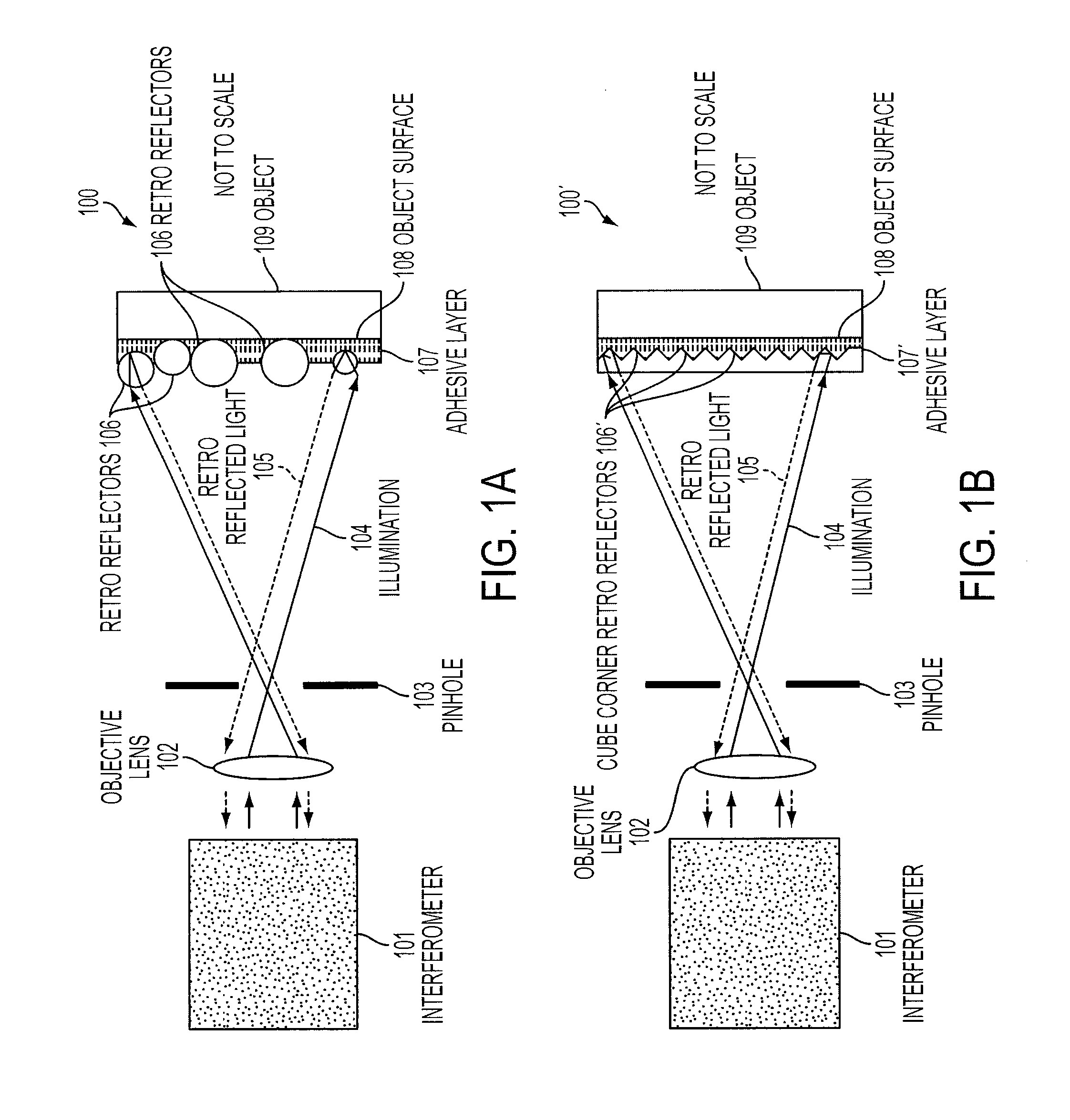
[0033]As will be explained, the present invention includes an improved holographic or speckle test (HOST) system that overcomes limitations of the conventional HOST systems by employing a retro-reflective surface treatment on one or more surfaces of the object under test and locating one or more sources coaxially with, or nearly coaxial to the optical axis of the receiving optics or the HOST system.

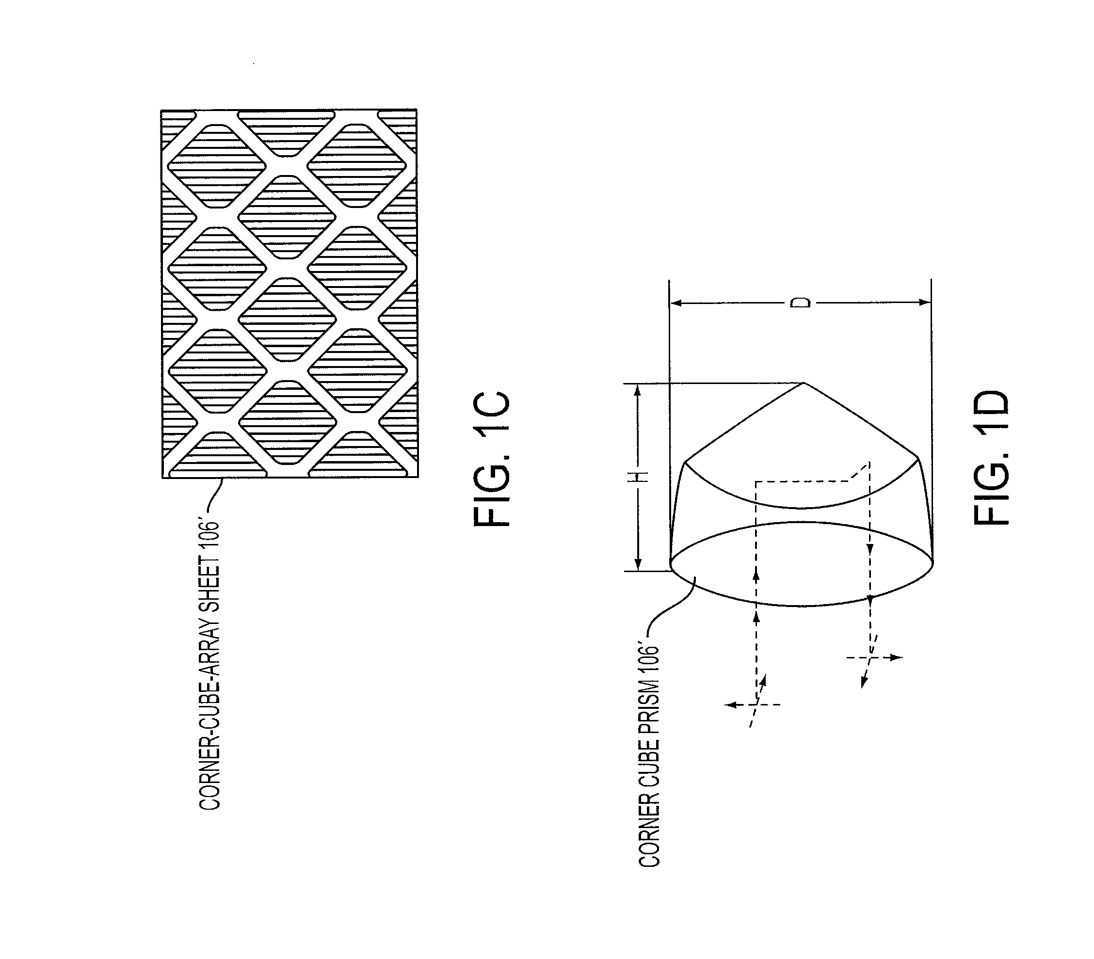
[0034]The retro-reflective surface treatment of the present invention includes several individual retro-reflective elements (RREs). These elements may include any combination of optical transparent dielectric spheres, cube corners, or other shaped reflective elements, where the size of the largest linear dimension of each element is typically less than 2 millimeters and more than 10 micrometers. The distribution of these elements may be tightly controlled or may be randomly distributed along at least one surface of the object under test.

[0035]The behavior of the surface of the object, whi...


PUM


Abstract

A system for measuring deformation of at least one surface of an object including an interferometer for receiving illumination reflected from the surface of the object, and a surface treatment disposed on the surface of the object for providing a retro-reflective patina. The retro-reflective patina is configured to reflect the illumination from the surface of the object. The retro-reflective patina is attached to the surface of the object and may include a plurality of cube corners, or a plurality of dielectric spheres, or a combination of cube corners and dielectric spheres. Impinging light onto the object is provided by an optical source that may be separate from or integral to the interferometer. The impinging light may be directed toward the object through an objective lens, which is also used for receiving the illumination from the object. Alternatively, the impinging light may be directed toward the object by first bypassing the objective lens.

Description

FIELD OF INVENTION[0001]The present invention is related, in general, to a system and method for measuring surface deformations, or changes in topology of an arbitrarily shaped object. More specifically, the present invention relates to a system and method for measuring the surface deformations by including a retro-reflective surface treatment on the surface of the object under measurement.BACKGROUND OF THE INVENTION[0002]Technologies for measuring surface deformations, or changes in topology in arbitrarily shaped objects include holography, electronic shearography and electronic speckle detection.[0003]These technologies are different from traditional interferometry. In a traditional interferometer, the measurement system is designed to emit a uniphase (typically spatially coherent) beam of light and receive a specular return of the light from an object. The object must have at least one optically smooth surface. The shape of the surface is such that it matches (or nearly matches) ...

Claims


Application Information

Patent Timeline
IPC IPC(8): G01B11/02
CPCG01B11/162G01B9/02095G01B2290/70G01B2290/15
Inventor OLCZAK, GENEO'DONOHUE, STEPHEN DDEY, THOMAS WMERLE, CORMIC K
Owner HARRIS CORP
Why Eureka
Try Eureka