
Organic electroluminescent device and material for organic electroluminescent device

a technology of organic electroluminescence and organic el, which is applied in the direction of luminescnet screens, discharge tubes, organic chemistry, etc., can solve the problems of rapid deterioration in the performance of organic el devices and the inability to put organic el devices to practical use, and achieve excellent electron-accepting properties and electron mobility, excellent performance, and enhanced electron-accepting properties

Active Publication Date: 2012-09-18
IDEMITSU KOSAN CO LTD +1
View PDF119 Cites 1 Cited by
  • Summary
  • Abstract
  • Description
  • Claims
  • Application Information

AI Technical Summary

Benefits of technology

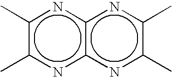
[0012]The compound according to the present invention has shown an excellent performance when used as a material for organic EL devices, particularly, as a hole injecting material therefor. Japanese Unexamined Patent Application Publication (hereunder simply referred to as “J.P. KOKAI”) No. Hei 03-232886 describes synthesis examples of dicyanotetraazanaphthalenes, but fails to give any specific descriptions as to the properties and application of each compound. In addition, J.P. KOKAI No. 2004-323434 reports that dicyanopyrazinoquinoxaline derivatives are excellent in electron-accepting properties and electron mobility. However, J.P. KOKAI No. 2004-323434 does not describe the performance or the like of an electronic device, for example, an organic EL device, achieved by using the compound in the device, and does not give any example of a case where the compound is used as the material for organic EL devices, particularly, as a hole injecting material therefor, unlike the present invention. Moreover, the compound according to the present invention can achieve optimization of the state of electrons, such as a further enhancement of electron-accepting properties, by combination with an azafluoranthene skeleton in addition to the portion of the structure (1), and also can provide changes in the state of a thin film, such as suppression of crystallization, by changing the three-dimensional structure of the molecule, so that the compound according to the present invention can improve the performance of the organic EL device. Specifically, the compound according to the present invention has high electron-accepting properties, and at the same time, is capable of forming a favorable thin film. Accordingly, the compound according to the present invention makes it possible to achieve an organic EL device that can be driven with a low voltage, has a reduced leakage current, and a longer lifetime, as well as suppressed increase in voltage.

Problems solved by technology

In addition, deterioration in the performances of the organic EL devices is rapid.
For these reasons, the organic EL devices have not yet been put to practical use.

Method used


Image

  • Organic electroluminescent device and material for organic electroluminescent device
  • Organic electroluminescent device and material for organic electroluminescent device
  • Organic electroluminescent device and material for organic electroluminescent device

Examples


example

Example 1

Synthesis of Compound (I)

[0215]3 g of 3,3′-diaminobenzidine (a) and 6.13 g of 5,6-dichloro-2,3-dicyanopyrazine (b) were reacted in 150 ml of acetonitrile under heat reflux for 10 hours. The reaction fluid was filtered at room temperature, and the resulting solid phase was washed with 100 ml of acetonitrile, 200 ml of water, and 50 ml of MeOH. The resulting solids were dried at 40° C. under reduced pressure for 4 hours to obtain 3.13 g of a crude product (c). The crude product (c) was subjected to the mass spectrometry (FDMS) and found to have m / e=466, so that the crude product (c) was identified as the intended product.

[0216]Further, 3 g of the crude product (c) and 3.21 g of DDQ (d) were reacted in 150 ml of THF at room temperature for 7 hours. The resulting reaction fluid was filtered, and the resulting solids were washed with 100 ml of THF and 30 ml of hexane. The resulting solid was dried at 40° C. under reduced pressure for 4 hours to obtain 2.77 g of a compound

[0217]T...

example 2

Synthesis of Compound (A-1)

[0220]10 g of acenaphthenequinone (e) and 8.8 g of 5,6-diamino-2,3-dicyanopyrazine (f) were reacted in 250 ml of pyridine under heat reflux for 18 hours. The reaction fluid was filtered at room temperature, and the resulting solid phase was washed with THF, and then further with acetonitrile. The resulting solids were dried at 60° C. under reduced pressure for 8 hours to obtain 11 g of a compound (A-1). The compound (A-1) was subjected to the mass spectrometry (FDMS) and found to have m / e=306, so that the compound (A-1) was identified as the intended product. The product was purified by the sublimation purification. The reduction potential of the purified compound was measured in the same manner as that for Example 1, and thereby found to be −0.48 V (vs Fc+ / Fc).

[0221]

example 3

Synthesis of Compound (3)

[0222]5 g of 4-trifluoromethyl-1,2-phenylenediamine (g) and 6.21 g of 5,6-dichloro-2,3-dicyanopyrazine (b) were reacted in 200 ml of acetonitrile under heat reflux for 10 hours. The reaction fluid was filtered at room temperature, and the resulting filtrate was concentrated to obtain 8.2 g of a crude product (h). The crude product (h) was subjected to the mass spectrometry (GC-MS) and found to have m / e=302, so that the crude product (h) was identified as the intended product. Further 6 g of the crude product (h) and 4.48 g of DDQ (d) were reacted in 100 ml of THF at room temperature for 8 hours. 400 ml of hexane was added to the resulting reaction fluid, and then a precipitate was collected by filtration. The resulting solids were dried at 60° C. under reduced pressure to obtain 3.33 g of a compound (3).

[0223]The compound (3) was subjected to the mass spectrometry (GC-MS) and found to have m / e=300, so that the compound (3) was identified as the intended prod...


PUM

PropertyMeasurementUnit
mol %aaaaaaaaaa
light transmittanceaaaaaaaaaa
transmittanceaaaaaaaaaa

Abstract

Disclosed is a novel compound useful as a constituent of an organic EL device. Also disclosed is a practical organic EL device using this compound. This organic EL device has low driving voltage, long life, and reduced leakage current. Specifically disclosed is a compound characterized by having at least one structure (1) shown below in a molecule. Structure (1)

Description

TECHNICAL FIELD[0001]The present invention relates to a novel material for organic electroluminescence (EL) devices and an organic EL device comprising the material, and relates to an organic EL device having a low driving voltage, a long lifetime, and a small leakage current.BACKGROUND ART[0002]The organic electroluminescence (EL) device using an organic material has been considered to be hopeful for use as a solid emitting type full color display device, which is cheap and has a large area and accordingly, there have widely been conducted a variety of investigations for the development of such devices. In general, the EL device comprises an emitting layer and a pair of electrodes sandwiching the emitting layer between them. The emission of light from the EL device is such a phenomenon that, when an electric field is applied between these electrodes, electrons are injected into the emitting layer from the side of the cathode, while holes are likewise injected into the layer from th...

Claims


Application Information

Patent Timeline
Patent Type & Authority Patents(United States)
IPC IPC(8): H01L51/54C07D471/00
CPCC07D487/04C07D519/00C09K11/06H01L51/0072C09K2211/1011C09K2211/1044H01L51/0052H01L51/006H01L51/0081H01L51/5048H10K85/615H10K85/633H10K85/6572H10K85/324H10K50/14H05B33/14H10K50/00
Inventor AOYAMA, YOSHIAKIMORISHITA, HIRONOBUHOSOKAWA, CHISHIOMATSUNAMI, SHIGEYUKIKIJIMA, YASUNORI
Owner IDEMITSU KOSAN CO LTD
Learn More