
Percutaneously retrievable stent assembly with fluid draining capability

a technology of stents and stents, which is applied in the field of percutaneously retrievable stent assemblies with expandable stents, can solve the problems of inability to use stricture dilation, catheters that do not provide any further increase in narrowing size, and formation of secondary strictures, so as to reduce the risk of stricture recurrence, improve dilatation, and safe and easy use

Inactive Publication Date: 2012-09-18
UNIV OF SOUTHERN CALIFORNIA
View PDF22 Cites 10 Cited by
  • Summary
  • Abstract
  • Description
  • Claims
  • Application Information

AI Technical Summary

Benefits of technology

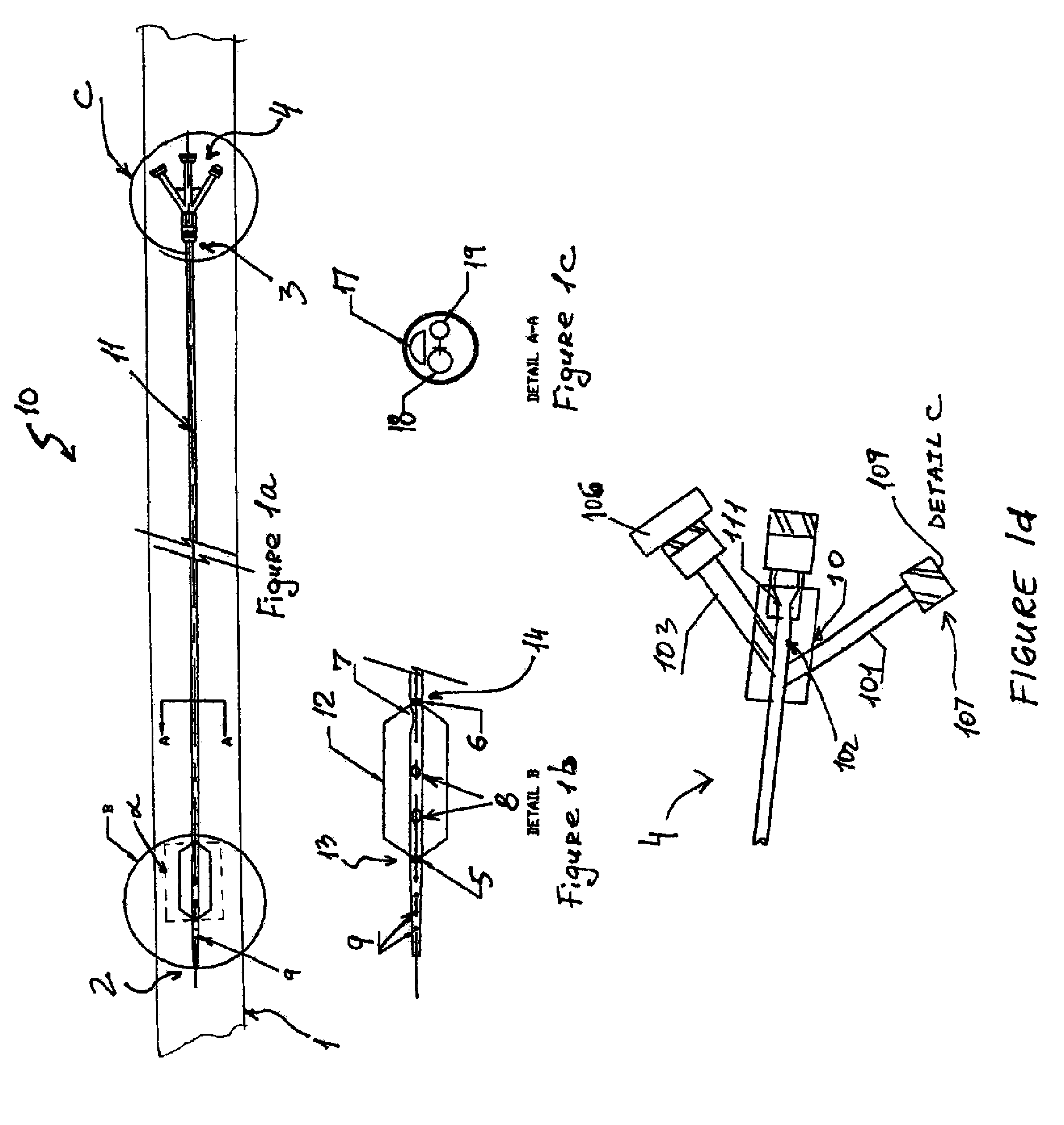
The present invention provides an improved stent assembly and method for treating bodily passages that can be placed within the passage to dilate it and remove fluid without damaging the passage. The stent assembly includes an expandable stent and a carrier for delivery or retrieval of the stent. The stent is attached to the carrier and can be expanded and deflated for easy removal. The stent assembly can be used to treat strictures and biliary stricture with minimal discomfort to the patient. The stent assembly combines the functions of dilatation and drainage, resulting in better dilatation, less sludge formation, lower risk of infection, and minimal pain. The stent can be removed through the same approach used for placement.

Problems solved by technology

Additionally, although conventional stents may be used for draining fluids, such as bile, they cannot be used for a stricture dilation.
Once inserted, the catheter does not provide any further increase in size of the narrowing without further intervention.
Furthermore, because the diameter of the catheter used to maintain the dilatation of the narrowed area is the same throughout the length of the catheter, a larger passage in the body is required, which may lead to complications, including infections and formation of secondary strictures.

Method used


Image

  • Percutaneously retrievable stent assembly with fluid draining capability
  • Percutaneously retrievable stent assembly with fluid draining capability
  • Percutaneously retrievable stent assembly with fluid draining capability

Examples


example 1

Clinical Application Of The Biliary Stent1

[0057]Patient is placed on spine in a decubitus position. The skin is prepared with betadine and the area of interest which is the upper abdomen lower torso on the right side is exposed and surrounded by sterile towels. 1% lidocane local anesthesia is injected in the 10th inter-costal space at the mid axillary line on the right side. A 15 cm long flexible 22 gauge needle with an external diameter of 0.8 mm and 30 degree cutting bevel is used for puncture towards the 11th vertebral body. The needle is advanced under direct fluoroscopic control in a parallel fashion to the X-ray table through the liver in the 10th inter-costal space toward the body of the 12th vertebrae until the tip of the needle reaches the midline at this level under fluoroscopy

[0058]The stylet of the needle is then removed, and a 10 mm syringe filled with diluted contrast with normal saline (50%) is attached to a clear flexible tubing which is connected to the needle hub....


PUM


Abstract

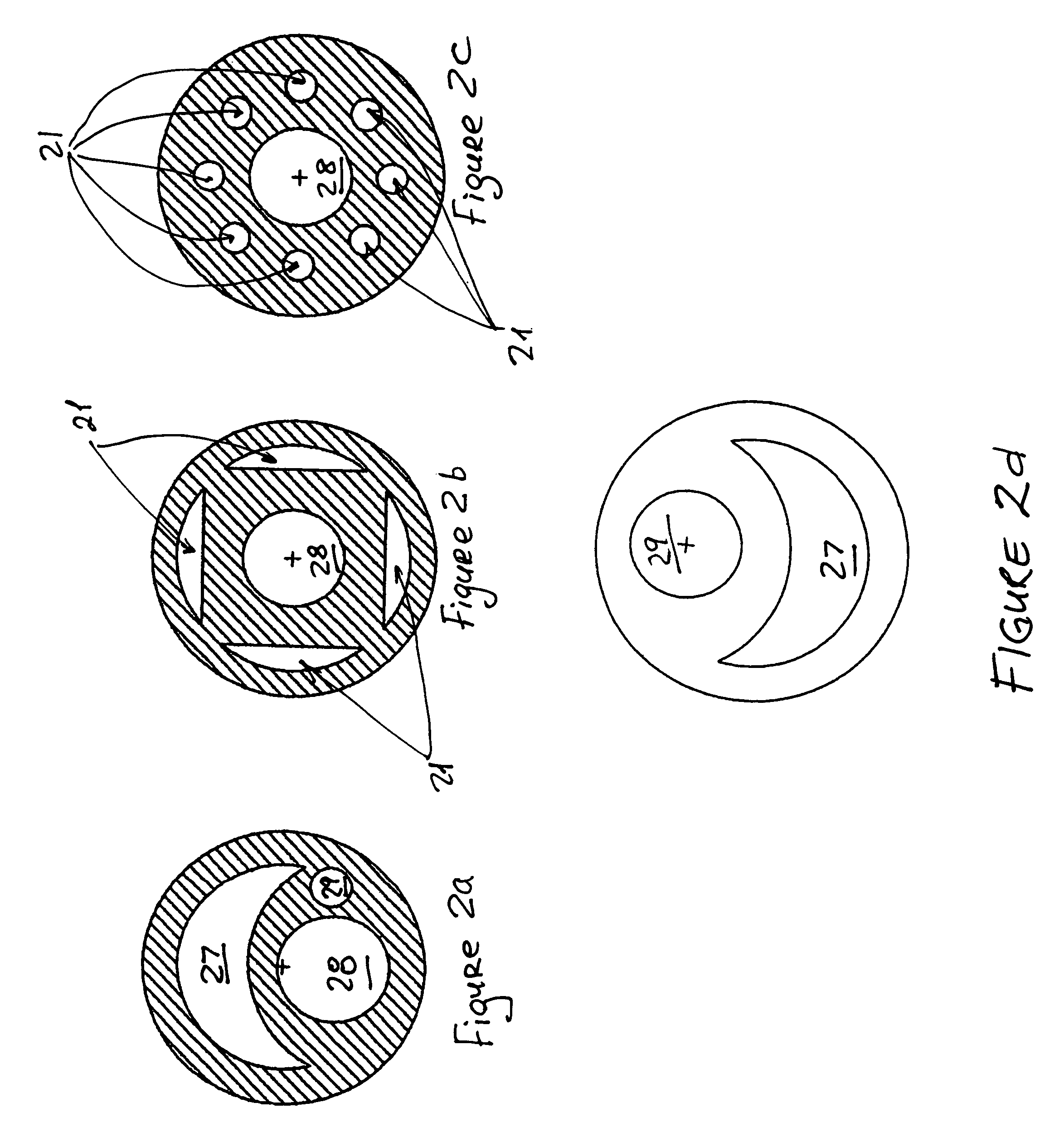
The present invention provides a stent assembly for expanding a bodily passage in a patient and draining a fluid therefrom. The assembly comprises at least one expandable stent and an elongated carrier for delivery or retrieval of the stent. The stent is circumferentially attached to a distal end of the carrier. The carrier defines at least two concentric lumens therethrough, a drainage lumen in fluid communication with the bodily passage for drainage of the fluid and an inflation lumen in fluid communication with the expandable stent. The invention also provides a method of expanding a bodily passage in a patient and draining a fluid therefrom. The method comprises providing a stent assembly of the present invention; inserting a guidewire into the bodily passage through the drainage lumen of the carrier; advancing the assembly along the guidewire until the assembly reaches a desired location; expanding the stent; and draining the fluid through drainage lumen of the carrier.

Description

[0001]This application claims priority to the U.S. Provisional Patent Application No. 60 / 591,787, filed on Jul. 27, 2004.FIELD OF THE INVENTION[0002]This invention relates to devices and methods for expanding a bodily passage in a patient and draining a fluid therefrom. In particular, the invention is directed to percutaneously retrievable stent assemblies with expandable stents.BACKGROUND OF THE INVENTION[0003]A number of disorders are characterized by formation of stenosis, strictures, or aneurysms that prevent normal passage and draining of fluids in body blood vessels and other tubular body structures, such as the esophagus, bile and kidney ducts, urinary tract, gastrointestinal (GI) tract, sinus pathway, and the tracheo-bronchial tree. When a tubular body structure becomes occluded, it is often desirable to dilate the occluded area and facilitate drainage of fluids therethrough. Although surgical methods are available for removing an occlusion or for a complete removal of a nar...

Claims


Application Information

Patent Timeline
Patent Type & Authority Patents(United States)
IPC IPC(8): A61M27/00A61F2/04
CPCA61F2/04A61M27/00A61M27/008
Inventor JABBOUR, NICOLASSHAOLIAN, SAMUEL M.
Owner UNIV OF SOUTHERN CALIFORNIA
Learn More