
Iron golf club head

a golf club and iron technology, applied in the field of iron golf club heads, can solve the problems of prone to deterioration and lack of vibration absorption effect of viscoelastic sheets, and achieve the effect of good adhesion durability and excellent vibration absorption

Inactive Publication Date: 2012-09-18
BRIDGESTONE SPORTS
View PDF25 Cites 64 Cited by
  • Summary
  • Abstract
  • Description
  • Claims
  • Application Information

AI Technical Summary

Benefits of technology

[0007]The present invention has as an object to provide an iron golf club head having good adhesion durability of a viscoelastic sheet opposing a faceplate and an excellent vibration-absorption effect.
[0015]According to the present invention, the viscoelastic body is fixed onto the back face of the faceplate, and also the backplate covers the viscoelastic body. The backplate has a flange extending out of the periphery of the viscoelastic body and fixed onto the back face of the faceplate. The viscoelastic body is, therefore, fully covered so as to be sealed by the backplate, so that it is not exposed to the atmosphere. For this reason, water does not splash thereon, and ultraviolet radiation does not directly strike, the viscoelastic body, and as a result, the durability of the viscoelastic body and durability of the adhesion of the viscoelastic body to the back face are good.
[0016]According to the present invention, since the flange of the backplate is fixed onto the faceplate, when a ball is hit (at the time of a golf shot), a part of the vibration generated in a peripheral portion of the faceplate propagates to the viscoelastic body through the backplate, so as to be absorbed. For this reason, the golf club head according to the present invention has an excellent vibration-absorbing effect.
[0017]In the case in which the viscoelastic body is housed in the recessed part of the backplate, it is possible to hold the viscoelastic body securely.
[0019]By the heel-side and toe-side parts of the flange extending to the heel and toe sides, respectively, vibration in the case of hitting at the heel side or the toe side of the faceplate can easily propagate through the viscoelastic body, and the vibration-absorption effect is high.

Problems solved by technology

For this reason, the edge face of the viscoelastic sheet is exposed to the atmosphere, so that it may be prone to deterioration, for example, by water or ultraviolet radiation, or so that it may peel from the back face of the faceplate.
Also, the viscoelastic sheet may lack a vibration absorbing effect because the viscoelastic sheet absorbs only vibration directly propagated from the faceplate.

Method used


Image

  • Iron golf club head
  • Iron golf club head
  • Iron golf club head

Examples


Embodiment Construction

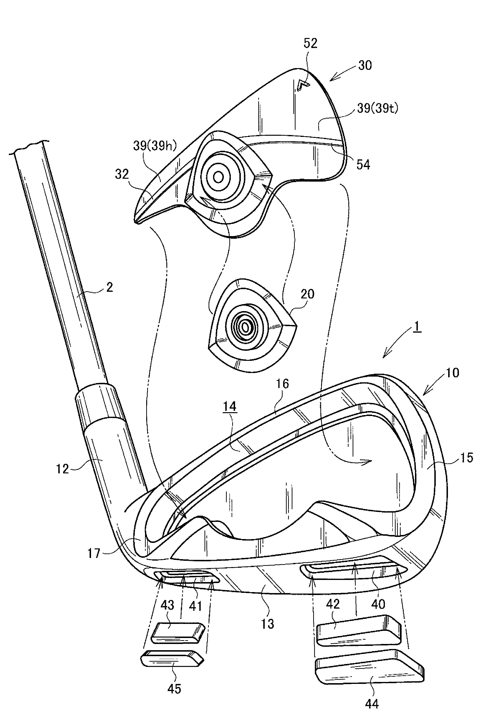
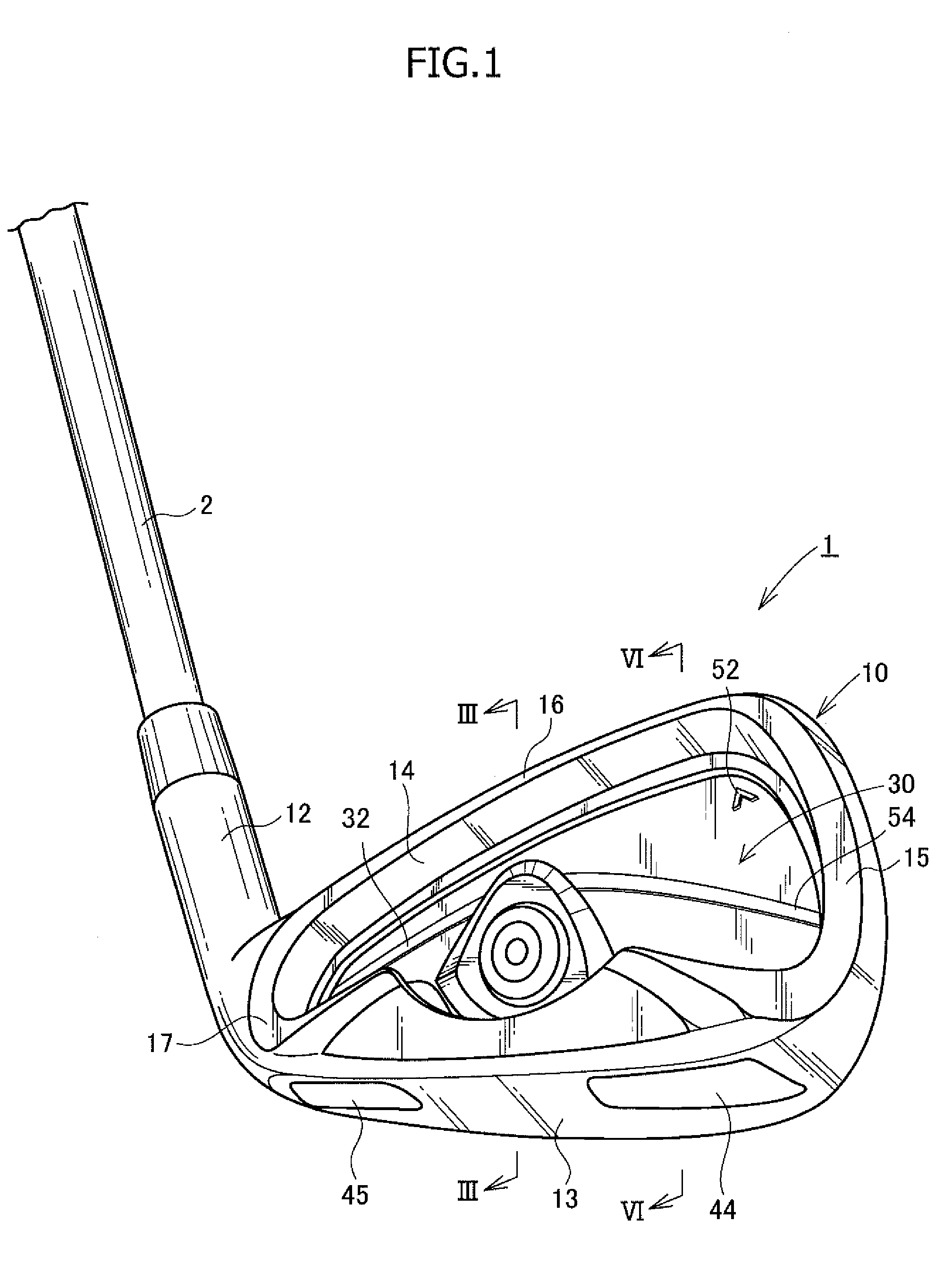
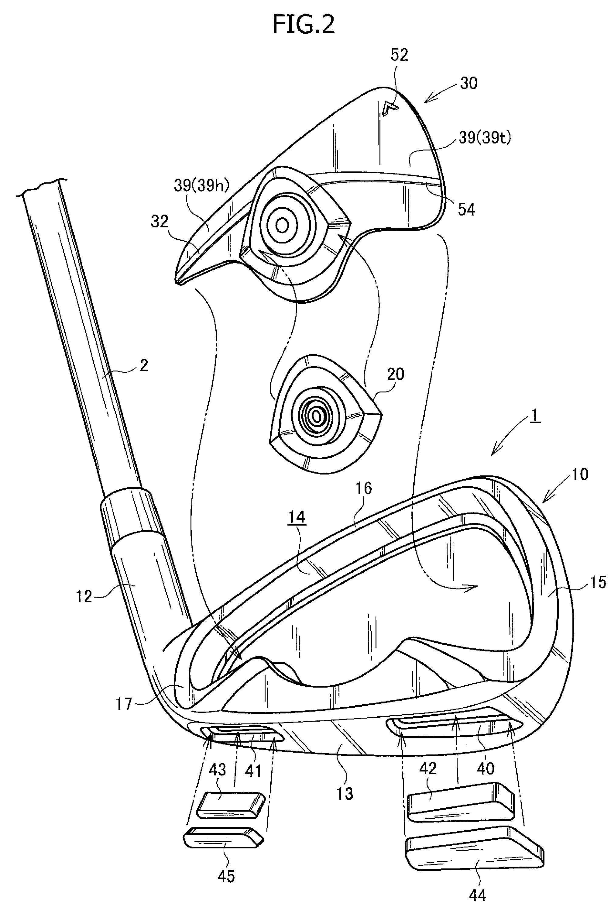
[0028]An embodiment of an iron golf club head in accordance with the present invention will now be described in more detail with reference to FIGS. 1 to 6.

[0029]An iron golf club head 1 is to be mounted on a tip of a shaft 2 of an iron golf club. The golf club head 1 includes a golf club head body 10, a viscoelastic body 20 fixed to a back face of a faceplate 11 of the golf club head body 10, and a nameplate (or backplate) 30 which covers the viscoelastic body 20 and is fixed to the back face of the faceplate 11.

[0030]The golf club head body 10 includes the faceplate 11, a hosel 12, and a sole 13. The faceplate 11 has a cavity 14 on the back face side thereof. The cavity 14 extends from a toe side to a heel side (i.e., a player's side). The periphery of the cavity 14 is surrounded by the sole 13, a toe-side protrusion 15, a top-side protrusion 16 and a heel-side protrusion 17, these protrusions 15-17 being backwardly protruding from the peripheral portion of the faceplate 11. The ba...


PUM


Abstract

An iron golf club head has a faceplate for hitting a golf ball, the faceplate having a back face; a viscoelastic body fixed onto the back face of the faceplate; and a backplate for sandwiching the viscoelastic body with the faceplate, the backplate having a flange that extends out of the periphery of the viscoelastic body and is fixed onto the back face of the faceplate.

Description

CROSS-REFERENCE TO RELATED APPLICATION[0001]This application claims priority of Japanese Patent Application No. 2009-180778 filed Aug. 3, 2009, which is incorporated herein by reference in its entirety.BACKGROUND OF THE INVENTION[0002]The present invention relates to an iron golf club head, and in particular, relates to an iron golf club head in which a viscoelastic body is disposed on and attached to a back face of a faceplate thereof.[0003]An iron golf club head at least includes a faceplate for hitting a golf ball, a sole, and a hosel. A shaft is inserted into and fixed to the hosel, thereby constituting an iron golf club.[0004]In order to absorb the impact or vibration generated in a golf club head when the ball is hit by the golf club, a viscoelastic material such as rubber may be attached to the golf club head or may be embedded in a hollow portion of the golf club head.[0005]Japanese Patent Application Publication No. 06-510689 discloses that an elliptical viscoelastic sheet ...

Claims


Application Information

Patent Timeline
Patent Type & Authority Patents(United States)
IPC IPC(8): A63B53/04A63B102/32
CPCA63B53/0475A63B59/0092A63B53/047A63B2053/0433A63B2053/045A63B2053/0408A63B60/54A63B53/0408A63B53/0433A63B53/045
Inventor TAKECHI, TAKAHARUHORII, DAISUKE
Owner BRIDGESTONE SPORTS
Learn More