
Valve for hydraulic fracturing through cement outside casing

a valve and cement technology, applied in the direction of fluid removal, borehole/well accessories, construction, etc., can solve the problems of prone to failure of current valve designs used in the completion method disclosed abov

Active Publication Date: 2012-09-18
INNOVEX DOWNHOLE SOLUTIONS INC
View PDF12 Cites 82 Cited by
  • Summary
  • Abstract
  • Description
  • Claims
  • Application Information

AI Technical Summary

Benefits of technology

[0005]The valve according to the invention overcomes the difficulties described above by isolating a sliding sleeve between an outer housing and an inner mandrel. A rupture disk in the inner mandrel ruptures at a selected pressure. Pressure will then act against one end of the sliding sleeve and shift the sleeve to an open position so that fracturing fluid will be directed against the cement casing. The sliding sleeve includes a locking ring nut to prevent the sleeve from sliding back to a closing position.

Problems solved by technology

Current designs for valves used in the completion method disclosed above are prone to failure because cement or other debris interferes with the opening of the valve after the cementing process has been completed.

Method used


Image

  • Valve for hydraulic fracturing through cement outside casing
  • Valve for hydraulic fracturing through cement outside casing
  • Valve for hydraulic fracturing through cement outside casing

Examples


Embodiment Construction

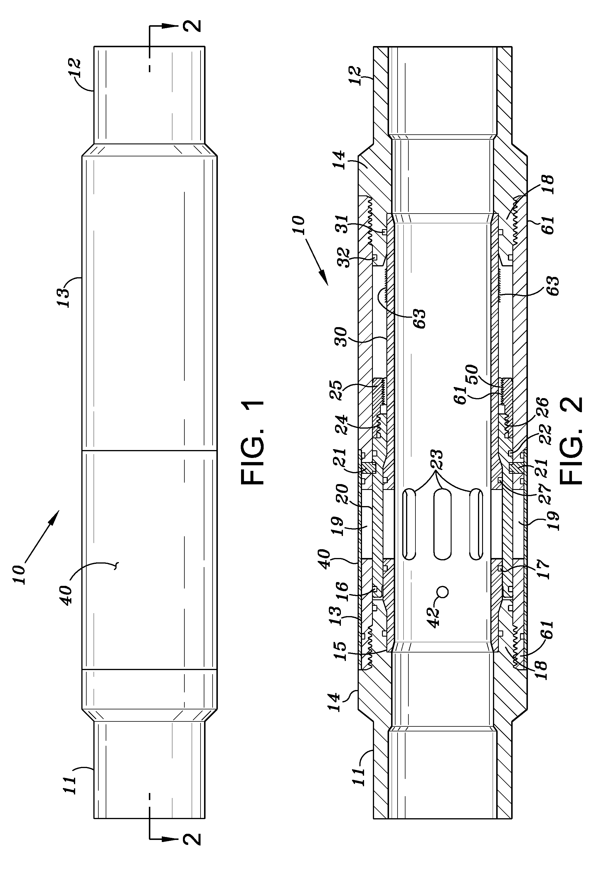
[0015]As shown in FIG. 1, an embodiment of valve 10 of the invention includes a main housing 13 and two similar end connector portions 11, 12.

[0016]Main housing 13 is a hollow cylindrical piece with threaded portions 61 at each end that receive threaded portions 18 of each end connector. End connectors 11 and 12 may be internally or externally threaded for connection to the casing string. As show in FIG. 2, main housing 13 includes one or more openings 19, which are surrounded by a circular protective cover 40. Cover 40 is made of a high impact strength material.

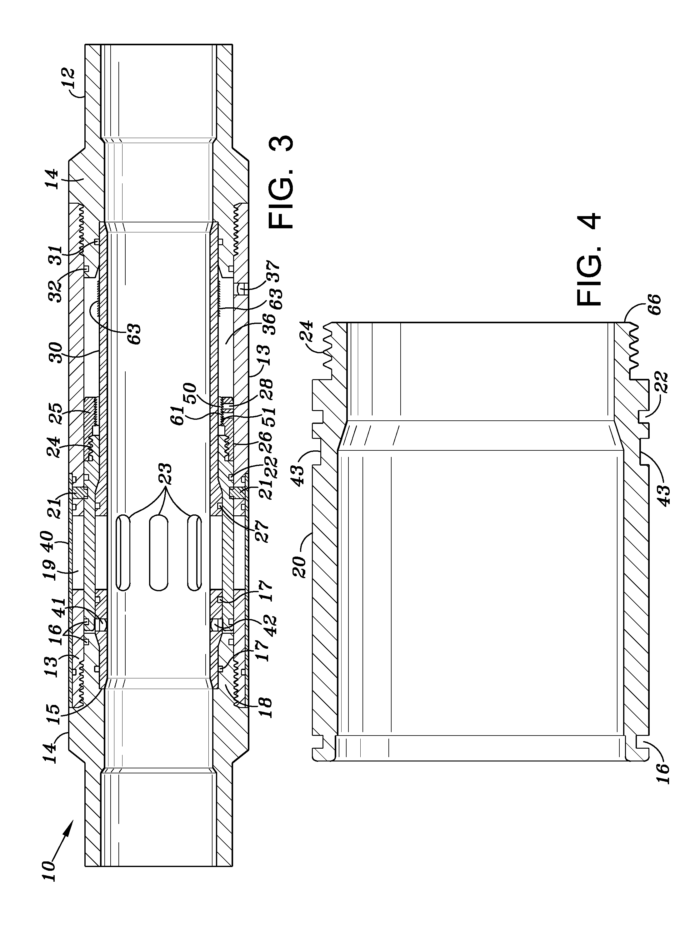
[0017]Valve 10 includes a mandrel 30 which is formed as a hollow cylindrical tube extending between end connectors 11, 12 as shown in FIG. 2. Mandrel 30 includes one or more apertures 23 that extend through the outer wall of the mandrel. Mandrel 30 also has an exterior intermediate threaded portion 51. One or more rupture disks 41, 42 are located in the mandrel as shown in FIG. 3. Rupture disks 41, 42 are located within pass...


PUM


Abstract

A valve for use in fracing through cement casing in a well allows for flow of cement down the well during the cementing process and in the open position allows for fracing fluid to be directed through the cement casing for fracturing the formation adjacent the valve. The valve is constructed so as to reduce the likelihood of the valve to jam as a result of cement or other foreign material.

Description

BACKGROUND OF INVENTION[0001]1. Field of the Invention[0002]This invention is directed to a valve utilized for hydraulically fracturing multiple zones in an oil and gas well without perforating the cement casing. A relatively new oil / gas well completion method involves the use of a valve that is installed as part of the casing string of the well and provides for cement flow within the casing when the valve element is in a closed position and allows for axial flow of fracturing fluid through the cement casing to fracture the formation near the valve. The invention disclosed herein is an improved valve used in this process.[0003]2. Description of Related Art[0004]Current designs for valves used in the completion method disclosed above are prone to failure because cement or other debris interferes with the opening of the valve after the cementing process has been completed. Portions of the sliding sleeve or pistons commonly used are exposed to either the flow of cement or the cement fl...

Claims


Application Information

Patent Timeline
IPC IPC(8): E21B34/14
CPCE21B34/102E21B34/103E21B2034/007E21B2200/06
Inventor SOMMERS, MICHAEL T.JACKSON, STEPHEN L.
Owner INNOVEX DOWNHOLE SOLUTIONS INC
Learn More