
Methods and devices for minimizing membrane fouling for microfluidic separators

a technology of microfluidic separator and membrane, which is applied in the direction of laboratory glassware, multi-stage water/sewage treatment, separation process, etc., can solve the problems of clogging or fouling of the separation device, and the time it takes to perform the separation techniqu

Active Publication Date: 2012-09-11
SCHLUMBERGER TECH CORP
View PDF31 Cites 22 Cited by
  • Summary
  • Abstract
  • Description
  • Claims
  • Application Information

AI Technical Summary

Benefits of technology

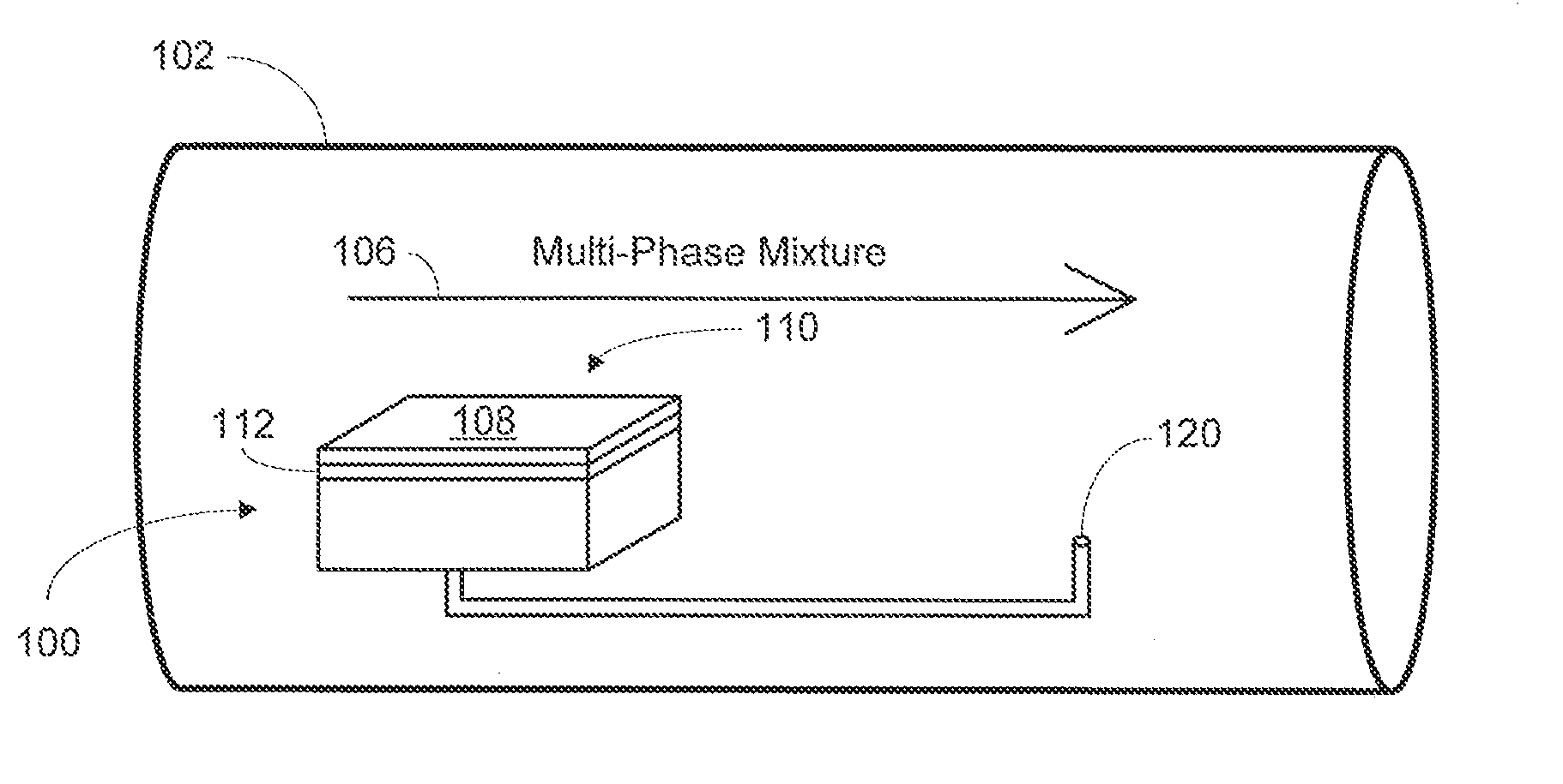
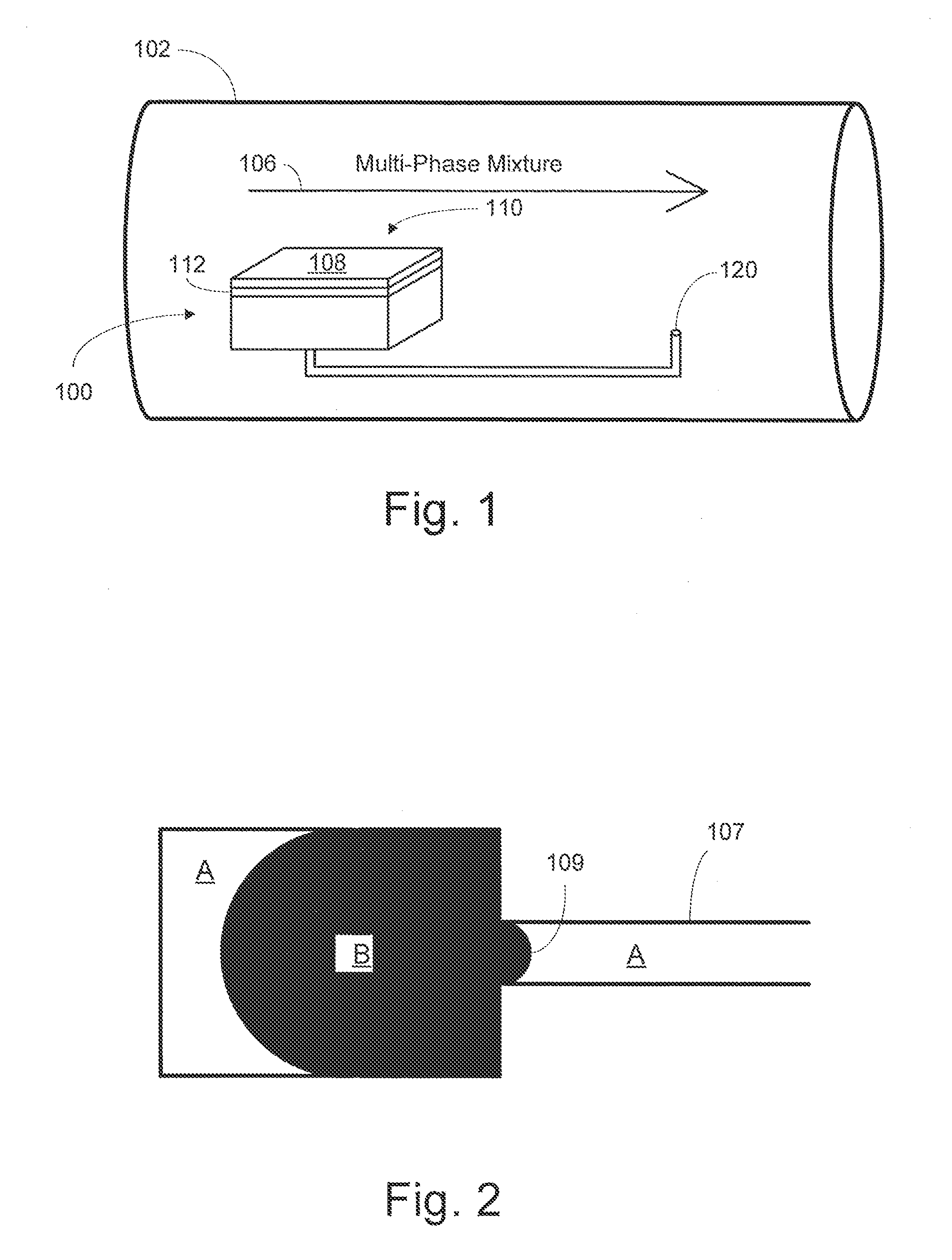
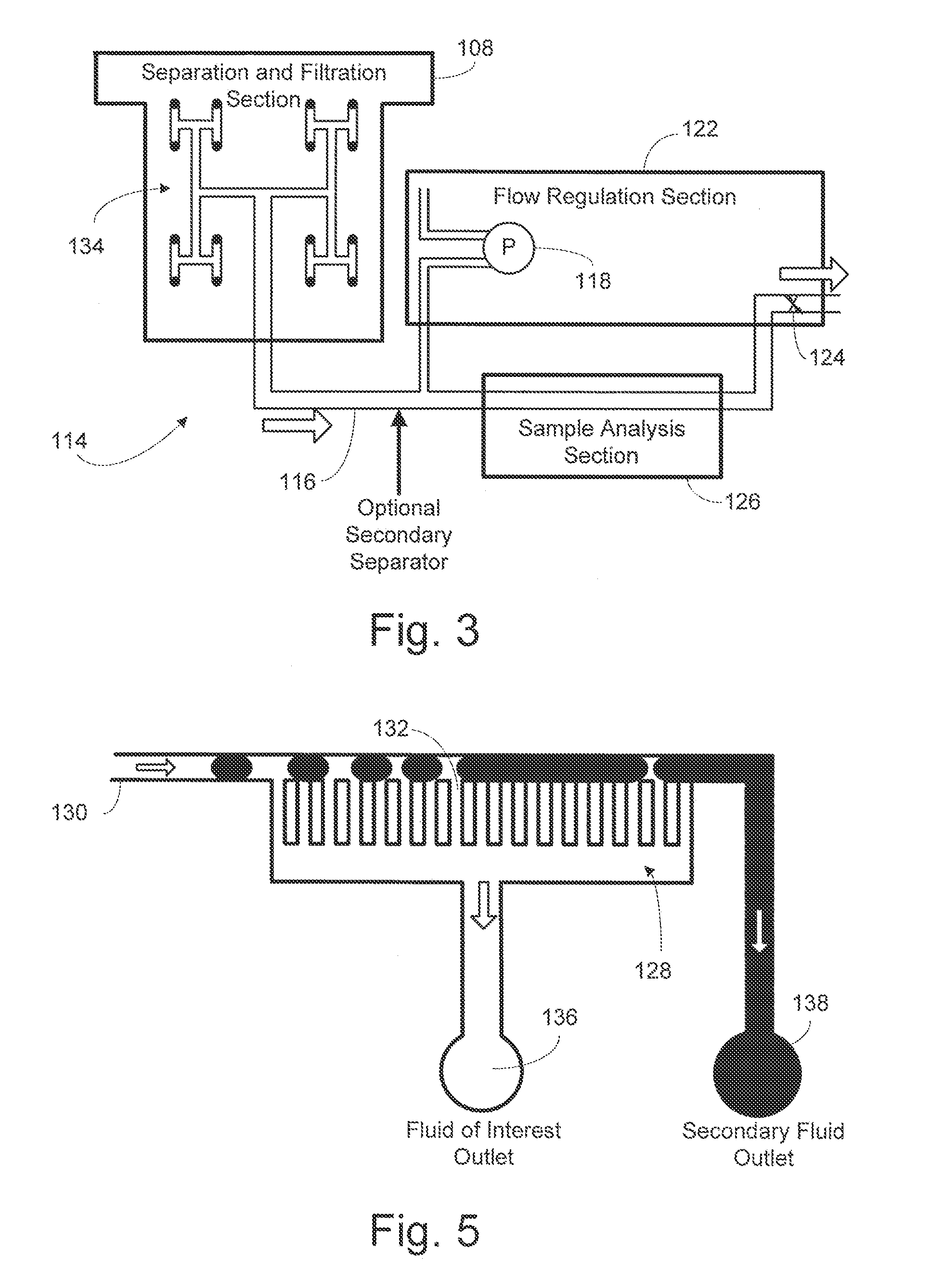
The present invention provides methods and apparatus for separating and analyzing fluids in real-time or near real-time from a subterranean environment. The invention minimizes fouling of the membrane by using a microfluidic device with a porous membrane and a power supply. The membrane is positioned tangent to the fluid flow stream, and channels are fabricated within the structure to direct the fluid flow stream and prevent fouling. The invention can be used in drilling, oilfield, and laboratory settings, and can measure properties of the fluid such as rheological properties, fluid composition, pressure, density, viscosity, temperature, and more. The invention provides a solution for analyzing fluids in real-time, minimizing fouling, and preventing clogging of the membrane.

Problems solved by technology

A major problem in accomplishing the separation of other components includes fouling or clogging of the separation device.
One drawback of conventional separation techniques is the time it takes to perform them.
Conventional separation techniques often take a long time, depending on the particular composition of the fluid.
For example, a fine emulsion may take months to separate by gravity, although a simple mixture may take only a few minutes.
Another drawback of conventional separation techniques is poor separation performance.
Conventional separation techniques usually do not perform a complete separation.
However, bringing sample fluids to the surface, transporting them to a laboratory, and separating the phase mixtures is time consuming, cost inefficient and provides only post-factum information.

Method used


Image

  • Methods and devices for minimizing membrane fouling for microfluidic separators
  • Methods and devices for minimizing membrane fouling for microfluidic separators
  • Methods and devices for minimizing membrane fouling for microfluidic separators

Examples


Embodiment Construction

[0039]The particulars shown herein are by way of example and for purposes of illustrative discussion of the embodiments of the present invention only and are presented in the cause of providing what is believed to be the most useful and readily understood description of the principles and conceptual aspects of the present invention. In this regard, no attempt is made to show structural details of the present invention in more detail than is necessary for the fundamental understanding of the present invention, the description taken with the drawings making apparent to those skilled in the art how the several forms of the present invention may be embodied in practice. Further, like reference numbers and designations in the various drawings indicated like elements.

[0040]According to embodiments of the invention, the invention includes a fluid separation method for performing fluid analysis. The fluid separation method includes providing a structure with a fluid analyzer and a power sup...


PUM

PropertyMeasurementUnit
transmembrane flow rateaaaaaaaaaa
shear rateaaaaaaaaaa

Abstract

A fluid separation method for performing fluid analysis of an unfiltered fluid. The fluid separation method includes providing a structure with a fluid analyzer and a power supply. Using a substrate for receiving a fluid flow stream of a multiphase mixture through a fluid sample inlet, wherein the substrate interconnects with the structure. Providing a membrane disposed across the fluid sample inlet for separating a fluid of interest from the multiphase mixture, wherein the fluid flow stream of the multiphase mixture has a shear rate that prevents a fouling of the membrane. Finally, the fluid separation method includes the substrate having fabricated channels, such that the fabricated channels are arranged substantially tangent to the fluid stream downstream of the porous membrane.

Description

[0001]This patent application claims priority from U.S. patent application Ser. No. 10 / 885,471 filed Jul. 6, 2004, incorporated by reference herein in its entirety. This patent application is a continuation-in-part from U.S. patent application Ser. No. 10 / 935,858, now U.S. Pat. No. 7,575,681, filed Sep. 8, 2004 (U.S. patent application Ser. No. 10 / 935,858 filed Sep. 8, 2004 is a continuation-in-part from U.S. patent application Ser. No. 10 / 885,471, now U.S. Pat. No. 7,799,278, filed Jul. 6, 2004), is incorporated by reference herein in its entirety.BACKGROUND OF THE INVENTION[0002]1. Field of the Invention[0003]The present invention relates to methods and devices for minimizing membrane fouling for microfluidic separators. In particular, methods and devices related to minimizing filter cake build-up on a membrane exposed to live oilfield fluids downhole.[0004]2. Background of the Invention[0005]The ability to reliably separate a fluid of interest can be very beneficial for oilfield,...

Claims


Application Information

Patent Timeline
Patent Type & Authority Patents(United States)
IPC IPC(8): B01D63/00B01D11/00
CPCB01D61/18B01D65/08B01D67/0062B01L3/502753B01L3/502784E21B43/38E21B49/081E21B49/10G01N1/4005B01D2321/2016B01L2200/0673B01L2300/0627B01L2300/0681B01L2300/0864B01L2300/0877B01L2300/161B01L2400/0487G01N33/28G01N2001/4016
Inventor ANGELESCU, DAN EUGENSALAMITOU, PHILIPPEWONG, JOYCERAGHURAMAN, BHAVANICLARK, BRIAN OLIVERHARRISON, CHRISTOPHERSULLIVAN, MATTHEWHAUSOT, ANDREASDE KERIZOUET, FLORENCE LE GALLIC
Owner SCHLUMBERGER TECH CORP
Learn More