System for charging a vapor cell

a vapor cell and charging system technology, applied in the field of chipscale vapor cells, can solve the problems of obscuring the transparent windows of the vapor cell, affecting the anodic bonding of the silicon substrate to the glass window, and reducing the exposure to atmospheric contaminants, so as to reduce the migration of sample materials and reduce the exposure

Active Publication Date: 2012-09-04
TELEDYNE SCI & IMAGING
View PDF2 Cites 51 Cited by
  • Summary
  • Abstract
  • Description
  • Claims
  • Application Information

AI Technical Summary

Benefits of technology

[0008]A system is disclosed for use in chip-scale vapor cells. Capillary or suction force is used to capture and deposit sample material into the vapor cell for charging and later interrogation. Capillary force results in reduced migration of sample material during manufacture and reduced exposure to atmospheric contaminants.
[0009]In one embodiment, a method is described that includes placing an alkali-filled capillary into a reservoir cell formed in a substrate, the reservoir cell in vapor communication with an interrogation cell in the substrate, and bonding a transparent window to the substrate on a common face of the reservoir cell and the interrogation cell to form a compact vapor cell. The capillary action in the capillary delays migration of alkali in the alkali-filled capillary from the reservoir cell into the interrogation cell during the bonding.

Problems solved by technology

Such exposure produces oxide and hydroxide contaminants which may later result in obscuration of the transparent windows of the vapor cell.
Additionally, anodic bonding of the silicon substrate to the glass windows may be frustrated by migration of the sample material itself to the bonding surface prior to or during charging and / or bonding, especially as such bonding surfaces are narrowed in an overall effort to miniaturize the devices.

Method used


Image

  • System for charging a vapor cell
  • System for charging a vapor cell
  • System for charging a vapor cell

Examples


Embodiment Construction

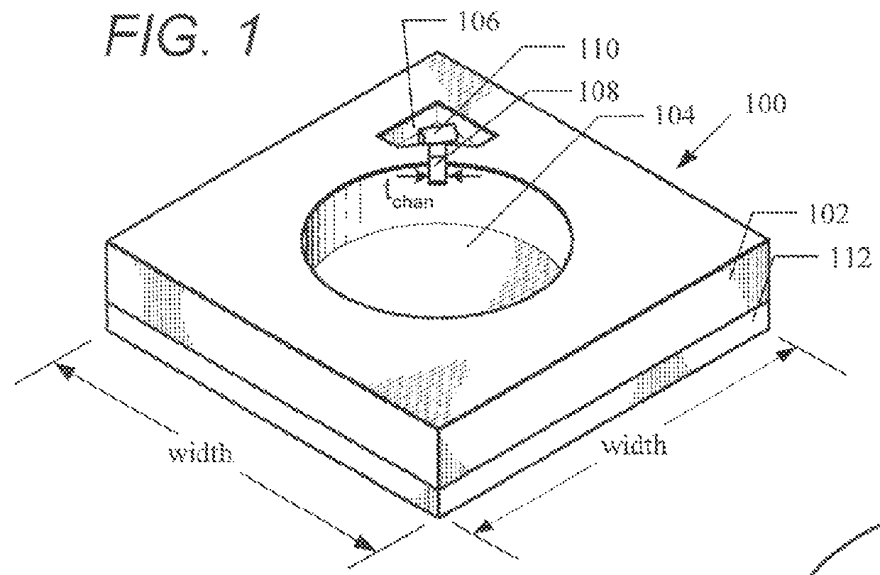
[0021]FIG. 1 illustrates one embodiment of a partially-assembled vapor cell 100 that uses as its foundation a substrate 102, preferably silicon crystal. An interrogation cell 104 having a generally cylindrical cross section is formed extending through opposite sides of the substrate 102. The interrogation cell 104 is in vapor communication with a reservoir cell 106, preferably through a trench 108. The reservoir cell 106 is sized to accept a cylindrical capillary 110 which delivers the sample material to the vapor cell for later gas interrogation, in accordance with one embodiment described, below. The reservoir cell 106 also provides a place for sample material, preferably rubidium (Rb) or cesium (Cs), that is not in vapor phase to condense on the coolest part of the vapor cell, outside an optical aperture for the interrogation cell 104, and provides a place outside of the optical aperture for any non-volatile Rb oxides and hydroxides residual from cell filling. The reservoir cell ...


PUM

PropertyMeasurementUnit
inner diameteraaaaaaaaaa
diameteraaaaaaaaaa
total resistanceaaaaaaaaaa

Abstract

A system is disclosed for charging a compact vapor cell, including placing an alkali-filled capillary into a reservoir cell formed in a substrate, the reservoir cell in vapor communication with an interrogation cell in the substrate and bonding a transparent window to the substrate on a common face of the reservoir cell and the interrogation cell to form a compact vapor cell. Capillary action in the capillary delays migration of alkali in the alkali-filled capillary from the reservoir cell into the interrogation cell during the bonding.

Description

[0001]This invention was made with Government support under Contract No. N66001-02-C-8025 awarded by the U.S. Navy Space and Naval Warfare Systems Center (SPAWAR). The Government has certain rights in this invention.BACKGROUND OF THE INVENTION[0002]1. Field of the Invention[0003]This invention relates to devices for vapor gas interrogation, and more particularly to chip-scale vapor cells.[0004]2. Description of the Related Art[0005]Advances in microelectromechanical systems (MEMS) have enabled a variety of miniaturized and chip-scale atomic devices used in, for example, gyroscopes, magnetometers and chip-scale atomic clocks. With reduced system dimensions come many advantages, including lower operating power and reduced manufacturing cost for the finished device. Of primary importance in many of these MEMS applications is an atomic vapor cell for use as a frequency-defining element, rather than traditional quartz-crystal resonators, for improved frequency stability.[0006]As is typic...

Claims


Application Information

Patent Timeline
Patent Type & Authority Patents(United States)
IPC IPC(8): H01S1/06H01S3/30
CPCG04F5/145Y10T137/8158
Inventor BORWICK, III, ROBERT L.SAILER, ALAN L.DANATALE, JEFFREY F.STUPAR, PHILIP A.TSAI, CHIALUN
Owner TELEDYNE SCI & IMAGING
Why Eureka
Try Eureka