
Short wavelength light source and optical device

a technology of short wavelength light source and optical device, which is applied in the direction of optics, lasers, instruments, etc., can solve the problems of difficult modulation of intensity with high efficiency, low energy conversion efficiency of gas lasers, etc., and achieve the effect of effective use of plurality

Inactive Publication Date: 2012-08-28
PANASONIC CORP
View PDF13 Cites 4 Cited by
  • Summary
  • Abstract
  • Description
  • Claims
  • Application Information

AI Technical Summary

Benefits of technology

"The present invention provides a short wavelength light source and an optical device that can effectively use multiple laser lights. The light source includes a laser light source that emits first laser light of a single polarization and a solid-state laser medium that is excited by the first laser light and emits second laser light with a different wavelength. A polarization switch switches over the polarization directions of the first and second laser lights to change the wavelength or intensity ratio of the emitted laser light. This allows for the effective use of multiple laser lights from a single source and simplifies the optical system configuration."

Problems solved by technology

These gas lasers, however, have a very low energy conversion efficiency of about 0.1%.
However, in the aforementioned laser light source, it is difficult to modulate the intensity with high efficiency, which is required in a light source for a laser display device.

Method used


Image

  • Short wavelength light source and optical device
  • Short wavelength light source and optical device
  • Short wavelength light source and optical device

Examples


first embodiment

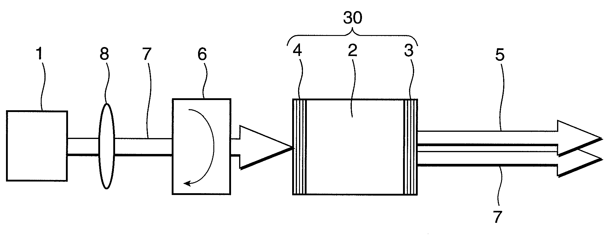
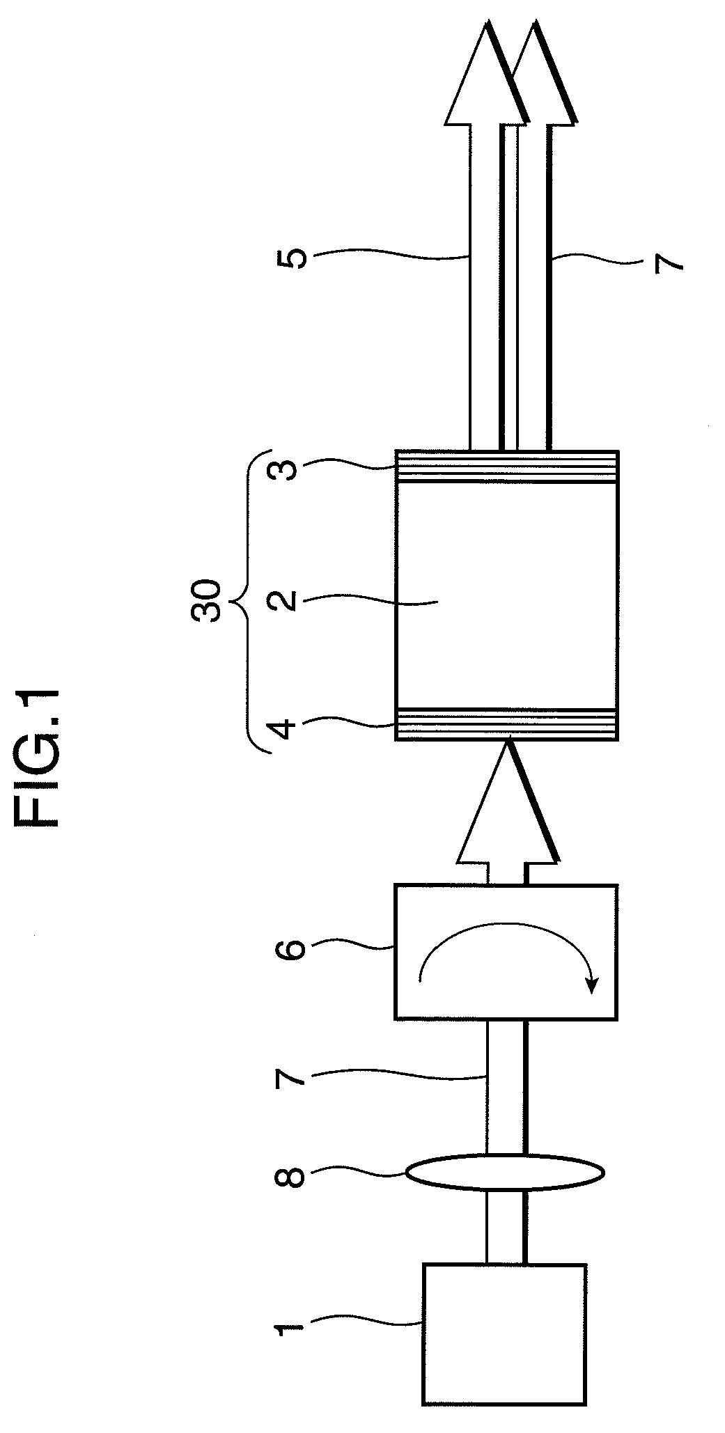
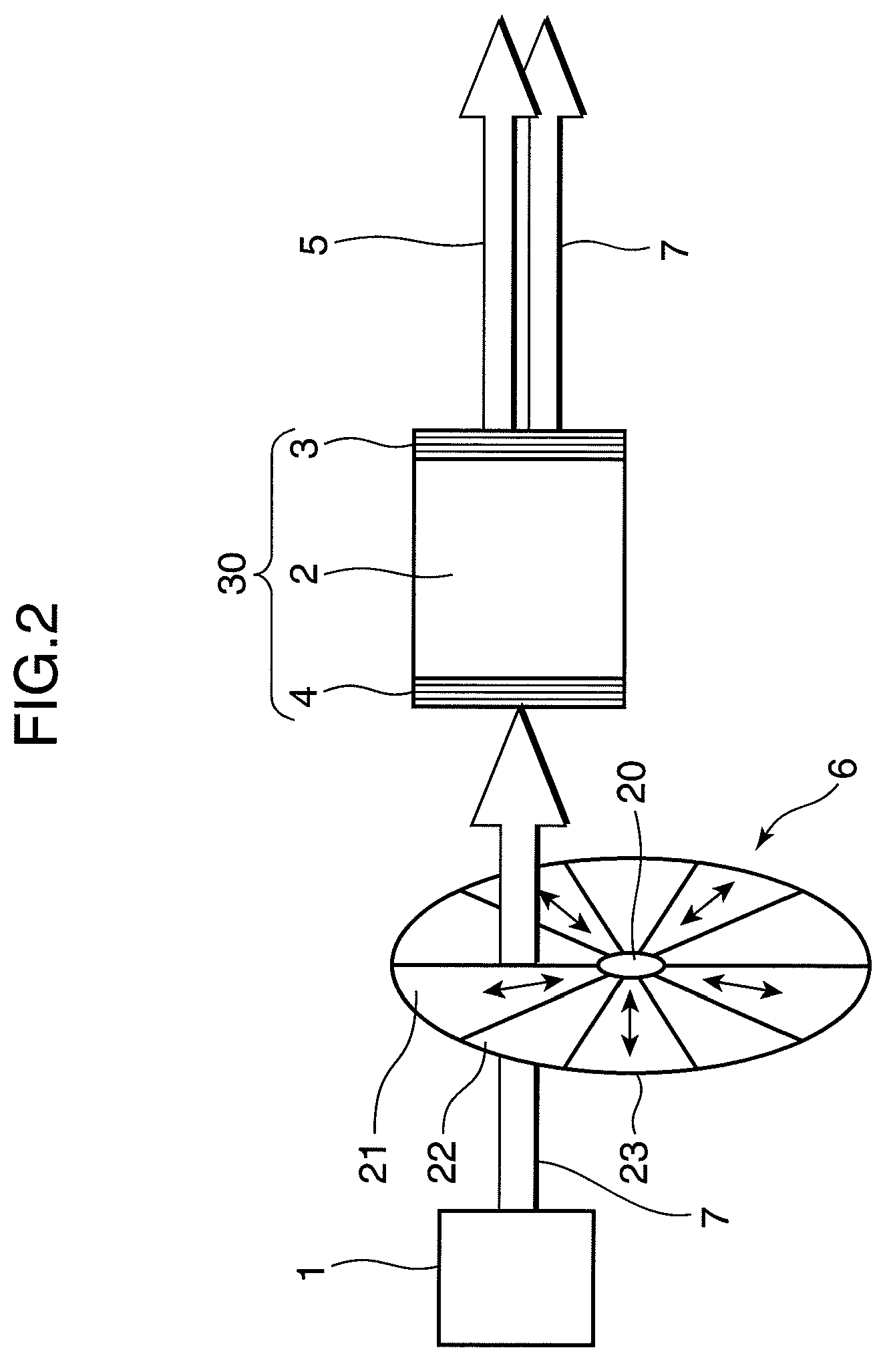
[0032]FIG. 1 is a diagram showing an arrangement of a short wavelength light source as the first embodiment of the invention. A short wavelength light source shown in FIG. 1 includes a GaN-based semiconductor laser 1, a laser medium 2, multilayer film mirrors 3 and 4, a polarization switch 6, and a light collecting optical system 8. An optical resonator 30 includes the laser medium 2 and the multilayer film mirrors 3 and 4.

[0033]The GaN-based semiconductor laser 1 is a multi-stripe semiconductor laser. Pump light 7 to be emitted from the GaN-based semiconductor laser 1 is linearly polarized light. The wavelength of the pump light 7 is near 440 nm. The output of the GaN-based semiconductor laser 1 is 5 W. The GaN-based semiconductor laser 1 emits the pump light 7 of a wavelength near 440 nm. The light collecting optical system 8 collects the pump light 7 emitted from GaN-based semiconductor laser 1.

[0034]The multilayer film mirror 4 is so designed as to transmit light of a wavelength...

second embodiment

[0094]In this section, described is a short wavelength light source incorporated with a doped fiber (a double clad fiber), as an arrangement of the second embodiment of the invention. FIG. 9 is a diagram showing an arrangement of the short wavelength light source as the second embodiment of the invention.

[0095]The short wavelength light source shown in FIG. 9 includes a GaN-based semiconductor laser 31, a double clad fiber 32 including a Pr3+-doped solid-state laser crystal as a core portion, a grating fiber 33, a polarization switch 34, and a reflection mirror 35.

[0096]The GaN-based semiconductor laser 31 emits pump light having a wavelength near 440 nm. Light of a wavelength near 440 nm which is emitted from the GaN-based semiconductor laser 31, is transmitted through the polarization switch 34 and the reflection mirror 35, and is guided into the double clad fiber 32. Excitation light is absorbed into Pr ions doped in the core portion of the double clad fiber 32. As a result of th...

third embodiment

[0114]In this section, a short wavelength light source as the third embodiment of the invention is described. FIG. 11 is a diagram showing an arrangement of the short wavelength light source as the third embodiment of the invention. In FIG. 11, like elements as in the short wavelength light source shown in FIG. 1 are indicated with like reference numerals, and description thereof is omitted herein. The short wavelength light source shown in FIG. 11 includes a GaN-based semiconductor laser 1, a multilayer film mirror 4, a light collecting optical system 8, a laser medium 2, and a polarization switch 19. An optical resonator 30 includes a laser medium 2, the multilayer film mirror 4, and the polarization switch 19.

[0115]In the short wavelength light source shown in FIG. 1, the polarization switch 6 is disposed between the light collecting optical system 8 and the multilayer film mirror 4. On the other hand, in the short wavelength light source shown in FIG. 11, the polarization switch...


PUM


Abstract

A GaN-based semiconductor laser (1) emits first laser light of a single polarization and having a first wavelength. An optical resonator (30) includes a solid-state laser medium which is excited by incidence of the laser light and which oscillates second laser light having a second wavelength different from the first wavelength. A polarization switch (6) switches over at least one of polarization directions of the first laser light and the second laser light to thereby change the wavelength of laser light to be emitted from the optical resonator (30) or the intensity ratio between a plurality of laser light to be emitted from the optical resonator (30). With the above arrangement, a plurality of laser light can be used effectively.

Description

TECHNICAL FIELD[0001]The present invention relates to a short wavelength light source using a solid-state laser medium, and an optical device incorporated with the short wavelength light source.BACKGROUND ART[0002]There has been proposed a laser display device incorporated with a laser light source for emitting laser light of three colors of RGB (red, green, and blue). Since laser light has monochromaticity, and is capable of expressing colors in a wide range, a laser display device incorporated with a laser light source is capable of displaying colorful images. A laser light source for emitting laser light of several watts is necessary to realize a large-screen laser display device by laser light of three colors of RGB. There has been used a gas laser such as a high-output Ar laser or Kr laser, as means for realizing the laser light source. These gas lasers, however, have a very low energy conversion efficiency of about 0.1%. Accordingly, a large-sized device including a cooling de...

Claims


Application Information

Patent Timeline
Patent Type & Authority Patents(United States)
IPC IPC(8): H01S3/30
CPCG03B21/14H01S3/09415H01S3/1022H04N9/3129H04N9/3161H04N9/3167H01S3/0612H01S3/0627H01S3/08009H01S3/08086H01S3/0809H01S3/10061H01S3/109H01S3/161H01S3/1613H01S3/1645H01S3/2383G03B21/2033G03B21/204G03B21/2073
Inventor MIZUUCHI, KIMINORIYAMAMOTO, KAZUHISAMIZUSHIMA, TETSURO
Owner PANASONIC CORP
Learn More