
Adaptive optics systems using pixilated microelectromechanical systems (MEMS)

a technology of microelectromechanical systems and adaptive optics, which is applied in the field of adaptive optics systems, can solve the problems of large-stroke deformable mirrors, unable to operate at slower speeds, and restricted wavefront correction capability of the system, so as to reduce transient effects, reduce the effect of transient effects, and increase the magnitude of tip/til

Active Publication Date: 2012-08-28
LOCKHEED MARTIN CORP
View PDF3 Cites 0 Cited by
  • Summary
  • Abstract
  • Description
  • Claims
  • Application Information

AI Technical Summary

Benefits of technology

Enables precise wavefront correction with larger angle tip / tilt capabilities and higher bandwidth operation, minimizing actuator movement and reducing transient effects by maintaining actuators at a mid-stroke position, thereby improving system performance.

Problems solved by technology

In an adaptive optics system where a deformable mirror (“DM”) is used, the wavefront correction capability of the system can often be restricted by the limited stroke of the mirror.
Large-stroke deformable mirrors are available, but are only able to operate at slower speeds (i.e., with lower bandwidth).

Method used


Image

  • Adaptive optics systems using pixilated microelectromechanical systems (MEMS)
  • Adaptive optics systems using pixilated microelectromechanical systems (MEMS)
  • Adaptive optics systems using pixilated microelectromechanical systems (MEMS)

Examples


Embodiment Construction

[0015]In the following detailed description, numerous specific details are set forth to provide a full understanding of the present invention. It will be apparent, however, to one ordinarily skilled in the art that the present invention may be practiced without some of these specific details. In other instances, well-known structures and techniques have not been shown in detail to avoid unnecessarily obscuring the present invention.

[0016]A pixilated MEMS spatial light modulator comprises a plurality of actuators, each of which can be actuated independently, without affecting neighboring actuators. Accordingly, such a modulator can be utilized to perform precise wavefront correction, and can moreover be used to provide tip / tilt or beam direction with large angles. This is due in part to the fact that when a wavefront or a portion thereof is shifted by 2π or a multiple thereof, the wavefront remains unchanged (for monochromatic light). Accordingly, even when the overall wavefront devi...


PUM

PropertyMeasurementUnit
phaseaaaaaaaaaa
modulusaaaaaaaaaa
tilt angleaaaaaaaaaa

Abstract

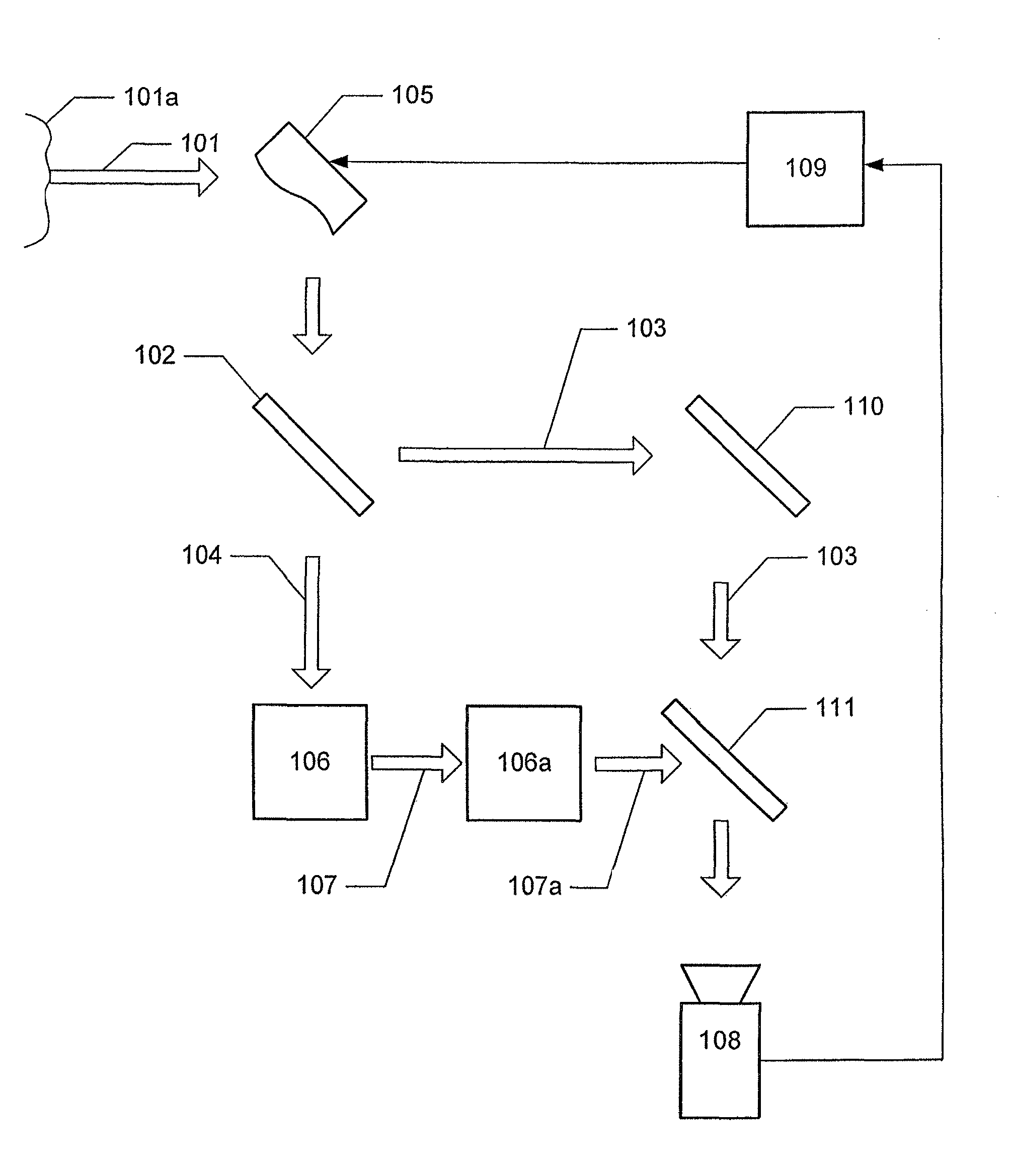
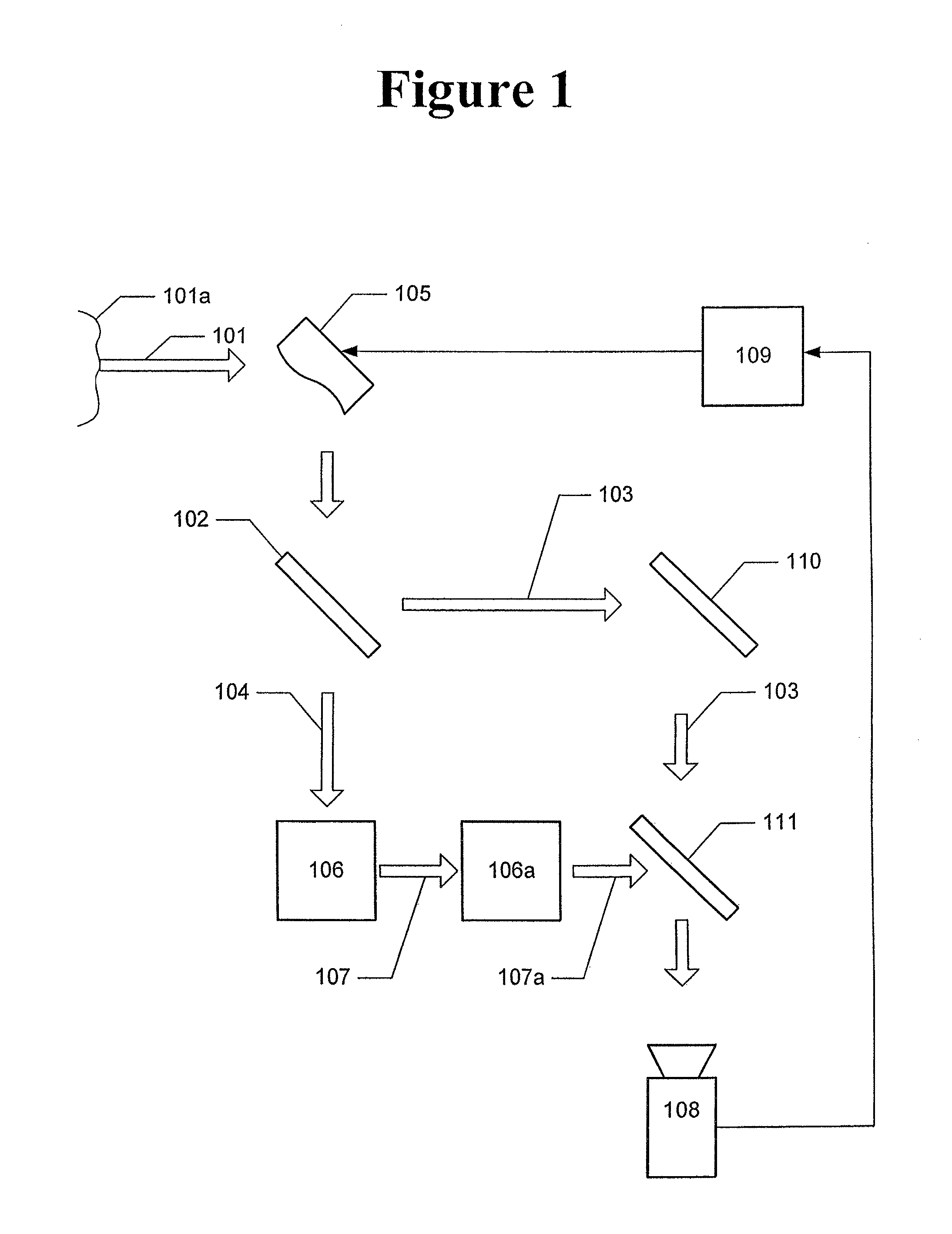
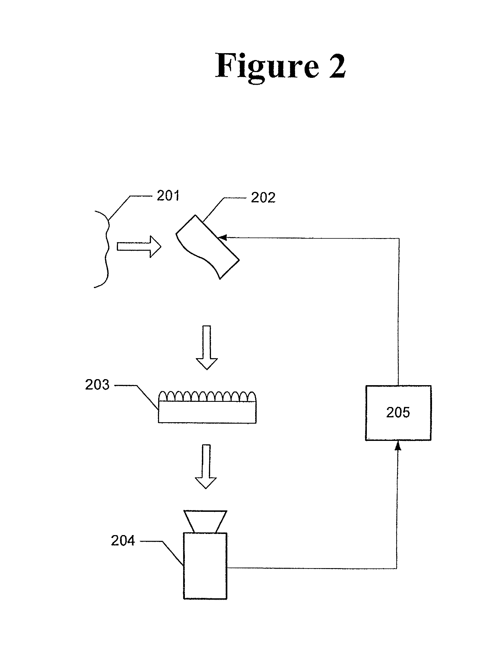
An adaptive optics system is provided, comprising a spatial light modulator configured to modulate an incoming beam with an aberrated wavefront, a beamsplitter configured to receive the modulated beam from the spatial light modulator and to divide the modulated beam into a measurement beam and a reference beam, a spatial filter configured to spatially filter the reference beam, and to interfere the spatially filtered reference beam with the measurement beam to form an interferogram, an imaging device configured to capture an image of the interferogram, and a processor configured to determine the aberrated wavefront and to provide control signals to the spatial light modulator to mitigate aberrations in the aberrated wavefront.

Description

CROSS-REFERENCES TO RELATED APPLICATIONS[0001]This application is a divisional application of U.S. patent application Ser. No. 12 / 258,262, filed on Oct. 24, 2008, which is hereby incorporated by reference in its entirety for all purposes.STATEMENT REGARDING FEDERALLY SPONSORED RESEARCH OR DEVELOPMENT[0002]Not applicable.FIELD OF THE INVENTION[0003]The present invention generally relates to adaptive optics systems and, in particular, relates to adaptive optics systems using pixilated microelectromechanical systems (MEMS).BACKGROUND OF THE INVENTION[0004]Adaptive optics (“AO”) are used to control deformable mirrors to compensate for phase aberrations introduced, for example, by the turbulence in the Earth's atmosphere or by the optical elements between a distant object and its local sensor. In an adaptive optics system where a deformable mirror (“DM”) is used, the wavefront correction capability of the system can often be restricted by the limited stroke of the mirror. In specific cas...

Claims


Application Information

Patent Timeline
Patent Type & Authority Patents(United States)
IPC IPC(8): G02F1/01G02B27/14
CPCG01J9/02G02B26/06G03H1/00G03H1/0443
Inventor CHANG, PETER H.SAAB, SAMI J.SHANKAR, NATARAJANKOONTZ, JOHN A.PTAK, MARK S.
Owner LOCKHEED MARTIN CORP
Learn More