
Laser and corner cube refractive-index structure parameter system

Inactive Publication Date: 2012-08-28
UNITED STATES OF AMERICA THE AS REPRESENTED BY THE SEC OF THE ARMY
View PDF2 Cites 8 Cited by
  • Summary
  • Abstract
  • Description
  • Claims
  • Application Information

AI Technical Summary

Benefits of technology

[0010]As a laser beam propagates the path from the transmitter to the target and back to the receiver, the beam encounters random fluctuations in the refractive index of the atmosphere, due primarily to temperature differences, as discussed above. Such refractive index fluctuations distort the beam's wavefront, resulting in a number of effects including spreading of the beam beyond that which occurs in free-space propagation, beam wander, and irradiance fluctuations due to random redistribution of energy in the beam. The beam spreading and irradiance fluctuations typically reduce the energy that is incident on the target and subsequently returned to the receiving aperture. As a result, atmospheric turbulence is a key consideration in returned power predictions.
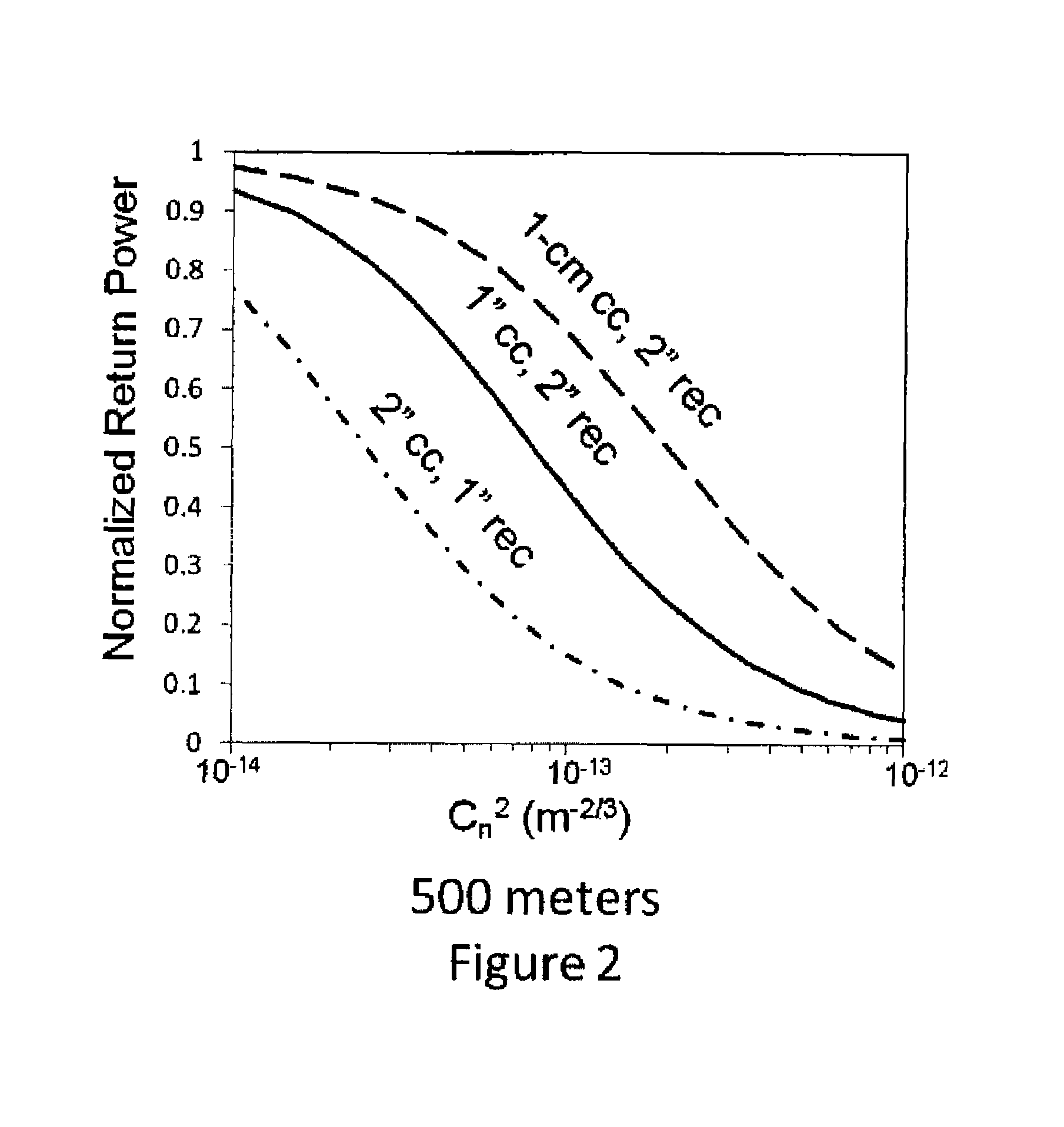
[0019]The transmission beams characteristics for a typical 500 meter propagation path include a power variable from 38 to 62 mW, a spot size at the transmitter of 5.5 mm, and a measured divergence angle (θT) of 1.45×10⁻³ rad. In order to measure the return beam power, the receiving optics included the beam splitter, mentioned above, that intercepted the retroreflected return beam, a focusing lens, and a narrowband spectral filter. To prevent distortion of the beam profile, the various lens should be of optical quality glass—with surface flatness of λ / 10 (λ=633 nm) and scratch-dig of 40-20 or better.

Problems solved by technology

Such refractive index fluctuations distort the beam's wavefront, resulting in a number of effects including spreading of the beam beyond that which occurs in free-space propagation, beam wander, and irradiance fluctuations due to random redistribution of energy in the beam.

Method used


Image

  • Laser and corner cube refractive-index structure parameter system
  • Laser and corner cube refractive-index structure parameter system
  • Laser and corner cube refractive-index structure parameter system

Examples


Embodiment Construction

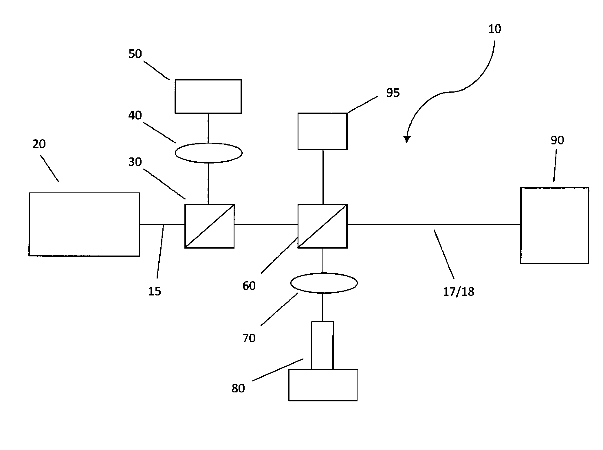
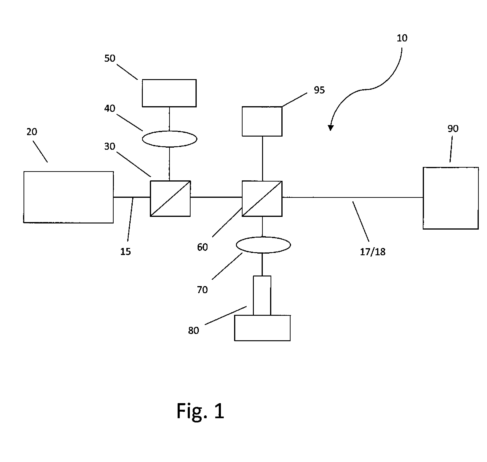
[0026]Referring to FIG. 1, a preferred embodiment of the subject invention includes a laser-and-corner cube system, 10, wherein the laser, 20, is a TEM00 laser which emits a spatial profile beam, 17, that is very nearly Gaussian (greater than 95%) and that does not change as it propagates, i.e. from when it emerges from the laser right into the far field. Such TEM00 laser beams can be generated by Nd:YAG lasers available from Litron Lasers NA, in Bozeman Mont., or CrystraLaser diode-pumped solid state continuous wave lasers, available from CrystaLaser, in Reno, Nev. The most preferred laser, 20, for measurements at ranges of approximately 500 meters is such a continuous laser with a power variable from 38 to 62 mW, a spot size at the transmitter of 5.5 mm, and a measured divergence angle (θT) of 1.45×10⁻³ rad, the wavelength should preferably be near IR, with a particularly preferred wavelength of 1064 nm.

[0027]Continuing to refer to FIG. 1, preferably a 90 / 10 beam splitter, 30, is ...


PUM


Abstract

A near-IR laser laser-and-corner cube system for determining the refractive-index structure parameter by providing the return power of the retroreflected laser beam from the corner cube, which return power correlates to the refractive-index structure parameter. The system is economical, physically containing only (1) the laser which emits a near-IR wavelength output beam, (2) a 50 / 50 splitter, to receive back the retroreflected return beam from the corner cube along the same optical axis as the output beam, in a monostatic configuration; (3) the target corner cube; (4) a receiving focus lens; (5) a spectral filter and (6) a power meter to provide the monostatic measurement of the return power. Critically the ratio of the area of the corner cube to that of the receiving focus lens is at least 1:2, to obtain meaningful power measurements—to correlate to pre-calculated refractive-index structure parameters.

Description

FEDERAL RESEARCH STATEMENT[0001]The inventions described herein may be manufactured, used and licensed by, or for the U.S. Government, for U.S. Government purposes.BACKGROUND OF INVENTION[0002]1. Field of the Invention[0003]The present invention relates to a method for determining optical turbulence, as measured by the refractive-index structure parameter, of the atmosphere along a beam propagation path using a simple laser and corner cube system and more particularly such a system involving a particularly sized receiver and corner cube combination.[0004]2. Related Art[0005]A laser beam propagating through the atmosphere encounters random refractive-index fluctuations. These random fluctuations are often referred to as optical or atmospheric turbulence. Such turbulence in the surface layer of the atmosphere, extending upward from the ground to a few tens of meters, is unstable if heat is rising from the ground, as is common during sunshine where the rising heat adds to the turbulenc...

Claims


Application Information

Patent Timeline
IPC IPC(8): G01N21/41G01N21/55
CPCG01N21/41G01N2021/4113
Inventor COLE, WALTER P.
Owner UNITED STATES OF AMERICA THE AS REPRESENTED BY THE SEC OF THE ARMY
Learn More