Fan and frame with sensor-supporting structure thereof
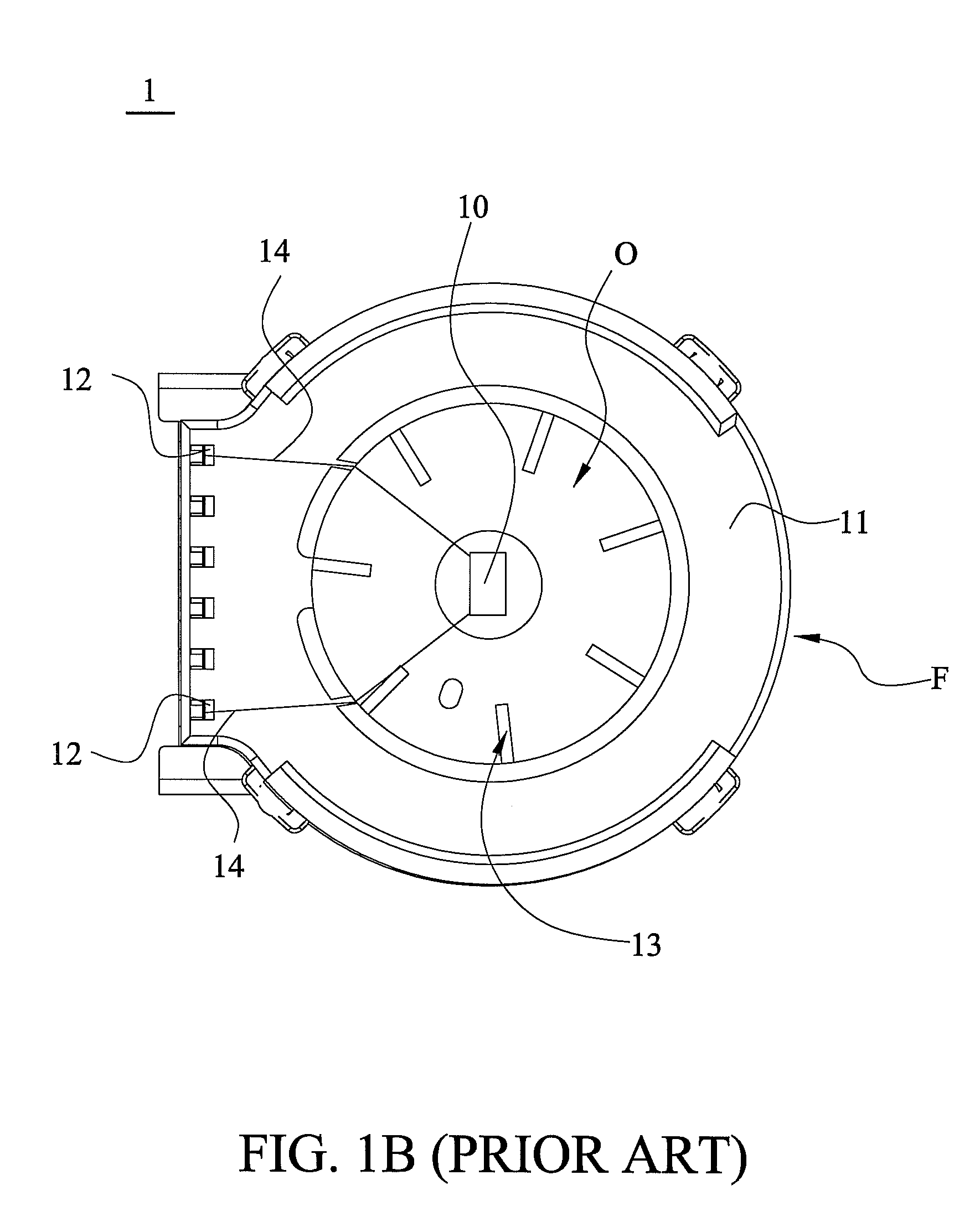
a fan and sensor technology, applied in the direction of machines/engines, stators, liquid fuel engines, etc., can solve the problems of vibration-induced damage of the sensor disposed on the fan, the detection temperature is often different from the actual temperature inside the vehicle, and the temperature sensor is dislocated, so as to prevent vibration-induced damage to the sensor on the fan, reduce the cost and assembly hours of the fan, and improve the effect of temperature detection
- Summary
- Abstract
- Description
- Claims
- Application Information
AI Technical Summary
Benefits of technology
Problems solved by technology
Method used
Image
Examples
first embodiment
[0020]In FIGS. 2A, 2B and 2C, the fan 2 of the first embodiment applied with a sensor 25 thereon, e.g. temperature or humidity sensor, includes a frame F2, a connecting portion 22 disposed outside of the frame F2, a rotor 26 having blades 23, and a stator 27. The frame F2 includes a main body 21 which is constituted by an upper main body f21 and a lower main body f22. The upper main body f21 of the frame F2 has an inlet O1, a sensor-supporting structure 24, and the sensor-supporting structure 24 is located close to the inlet O1. Airflow enters the inner of the fan 2 via the inlet O1 of the upper main body f21 of the frame F2. The sensor-supporting structure 24, extending from the upper main body f21 toward the inlet O1 where the airflow passes, is utilized to support the sensor 25. The sensor 25 includes leadwire portions W1 connected to the connecting portion 22 and an element portion S1 connected to the leadwire portions W1. In this embodiment, the connecting portions 22 are sever...
second embodiment
[0023]Referring to FIGS. 3A and 3B, a fan 3 of a second embodiment, applied with a sensor 35 thereon, includes a frame F3, a connecting portion 32 disposed outside of the frame F3, a rotor 36 having blades 33, and a stator (not shown) located in the frame F3. The frame F3 is formed by an upper main body f31 and a lower main body f32. The upper main body f31 includes an inlet O2 and a sensor-supporting structure 34. The sensor-supporting structure 34 connects with the upper main body f31. However, it is to be understood that the present invention is not limited to the disclosed embodiment. The sensor-supporting structure 34 can be in any sites of the frame F2 as long as the sensor-supporting structure 34 is located close to the inlet O2 to detect the airflow. In addition, the inlet O2 can also be located in the lower main body f32. Moreover, the frame F3 can also be integrally formed as a single piece without combining the upper main body f31 and the lower main body f32. Airflow ente...
PUM
 Abstract
Description
Claims
Application Information
 - R&D
- Intellectual Property
- Life Sciences
- Materials
- Tech Scout
- Unparalleled Data Quality
- Higher Quality Content
- 60% Fewer Hallucinations
Browse by: Latest US Patents, China's latest patents, Technical Efficacy Thesaurus, Application Domain, Technology Topic, Popular Technical Reports.
© 2025 PatSnap. All rights reserved.Legal|Privacy policy|Modern Slavery Act Transparency Statement|Sitemap|About US| Contact US: help@patsnap.com


