
Reflective triplet optical form with external rear aperture stop for cold shielding

a triplet optical and cold shielding technology, applied in the direction of mirrors, instruments, mountings, etc., can solve the problems of reduced image quality, increased cost, and inability to meet the requirements of applications,

Active Publication Date: 2012-08-21
RAYTHEON CO
View PDF21 Cites 12 Cited by
  • Summary
  • Abstract
  • Description
  • Claims
  • Application Information

AI Technical Summary

Benefits of technology

The present invention provides a reflective triplet optical form with a rear aperture stop for cold shielding, which can improve the quality of infrared images by reducing noise. The system includes a primary mirror, secondary mirror, tertiary mirror, and image plane, with the aperture stop located between the last optical element and the image plane. The aperture stop can also be located above or to the side of the secondary mirror. The invention also includes a cold cavity with a window coincident with the aperture stop and having boundaries up to and between the aperture stop and the focal plane. The method of imaging objects in the system involves reflecting radiation in a first direction relative to the optical axis, reflecting it in a second direction relative to the optical axis, reflecting it in a third direction relative to the optical axis, and forming an image of the distant objects. The invention provides better cold shielding up to and between the aperture stop and the focal plane.

Problems solved by technology

However, refractive optical elements are not optimum for applications that require a large aperture.
Such refractive optical elements (e.g., lenses) are difficult to manufacture and result in greater expense, because it is necessary to manufacture large lens elements for these systems.
The large lens elements also tend to flex, resulting in a decrease of image quality.
Moreover, refractive optical elements by their nature may also absorb radiation because they are not completely transparent at certain wavelengths.
In addition, reflective optical elements do not allow light to pass through, but rather, reflect radiation at most wavelengths, resulting in less loss of radiation.
This arrangement results in the occlusion of a significant portion of the radiation entering the system from a distant object, a restriction of the field of view of the system and a constraint on the power distribution between optical elements.

Method used


Image

  • Reflective triplet optical form with external rear aperture stop for cold shielding
  • Reflective triplet optical form with external rear aperture stop for cold shielding
  • Reflective triplet optical form with external rear aperture stop for cold shielding

Examples


Embodiment Construction

[0025]The present invention will now be described more fully with reference to the accompanying drawings, in which exemplary embodiments thereof are shown. The invention may, however, be embodied in many different forms and should not be construed as being limited to the embodiments set forth herein; rather, these embodiments are provided so that this disclosure will be thorough and complete, and will fully convey the concept of the invention to those skilled in the art.

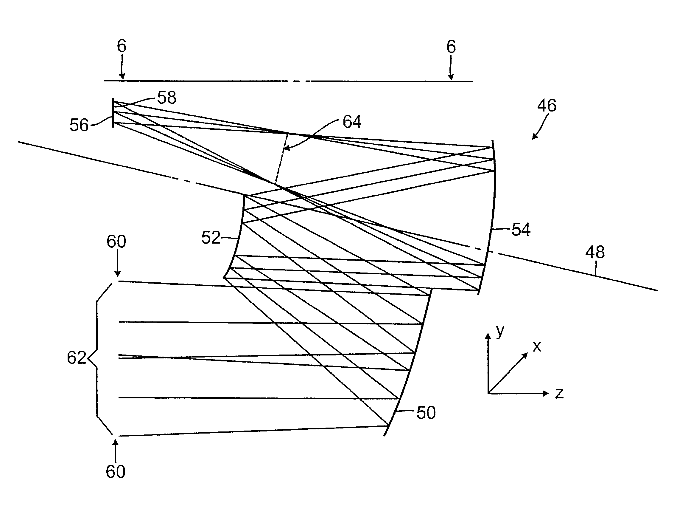
[0026]Accordingly, there is presented a reflective triplet optical form with a rear aperture stop for cold shielding in accordance with embodiments of the present invention. The system may be utilized for providing images of distant objects. Using all-reflecting optical elements, the system is configured such that the aperture stop of the optical system is between the last optical element and the image plane. With the aperture stop in this position, the image plane may be cold shielded more effectively than prior art...


PUM


Abstract

An all-reflecting, non-relayed optical system having an aperture stop and an optical axis and configured to provide images of objects. The system includes a positive power primary mirror configured to receive radiation from the objects, a negative power secondary mirror configured to receive the radiation reflected from the primary mirror and a positive power tertiary mirror configured to receive the radiation reflected from the secondary mirror. The system further includes a focal plane configured to receive the radiation reflected from the tertiary mirror and to form an image of the objects. The aperture stop of the optical system is located between the tertiary mirror and the image plane. Accordingly, the image plane may be cold shielded to prevent or reduce radiation reflected from the optical elements that interferes with the desired image.

Description

BACKGROUND[0001]1. Field of the Invention[0002]The present invention relates to a reflective triplet optical form with an external rear aperture stop for cold shielding.[0003]2. Description of the Related Art[0004]Electromagnetic radiation imaging systems have been widely used to image objects at long distances by telescope in the visual and infrared portions of the radiation spectrum.[0005]Generally, optical elements of long distance telescopes may be refractive or reflective. Refractive optical elements are generally effective in controlling and / or preventing aberrations, and may be used in a variety of applications. However, refractive optical elements are not optimum for applications that require a large aperture. Such refractive optical elements (e.g., lenses) are difficult to manufacture and result in greater expense, because it is necessary to manufacture large lens elements for these systems. The large lens elements also tend to flex, resulting in a decrease of image quality...

Claims


Application Information

Patent Timeline
Patent Type & Authority Patents(United States)
IPC IPC(8): G02B23/00
CPCG02B17/0626G02B17/0636G02B2207/121G02B5/006
Inventor COOK, LACY
Owner RAYTHEON CO
Learn More