
Replacement window and door sealing fin and method

a technology for replacing windows and doors, applied in window/door frames, special door/window arrangements, building repairs, etc., can solve problems such as premature failure of building structures, damage to the nailing fin, and damage to the other end,

Active Publication Date: 2012-08-21
MILSTEAD ROBERT J
View PDF17 Cites 2 Cited by
  • Summary
  • Abstract
  • Description
  • Claims
  • Application Information

AI Technical Summary

Benefits of technology

[0007]It is an object of the invention to provide a replacement window and door sealing fin and method that prevents moisture, air, and insects from penetrating the interior materials of a structure.
[0008]The present invention provides an economical replacement window and door sealing fin that is easy to install and prevents moisture, air and insects from penetrating sheetrock, drywall and other interior materials. The sealing fin is elongated, and comprises a central fin portion intersecting a crosspiece portion perpendicular thereto, the two portions together generally form a “T” shape. The crosspiece and central fin are each formed from thin, flat, generally rectangular sheets of flexible material. In one aspect of the invention, the central fin is coupled to the crosspiece such that said central fin may be folded to lay flat against the crosspiece. When the central fin is in this folded position, the sealing fin may be easily rolled.

Problems solved by technology

Water damage around such openings is one of the most common factors leading to premature failure in building structures.
In the process of removing the window, the nailing fin is also removed or otherwise damaged.
Unfortunately, the exterior material of the structure often prevents the replacement window from being secured by nailing fins in the same manner as the original window.
This method, however, is ineffective in preventing water infiltration between the structure wall and the exterior material.
Not surprisingly, replacement windows often allow moisture, air, and insects to penetrate interior materials of the structure such as structural framing, sheetrock and drywall.

Method used


Image

  • Replacement window and door sealing fin and method
  • Replacement window and door sealing fin and method
  • Replacement window and door sealing fin and method

Examples

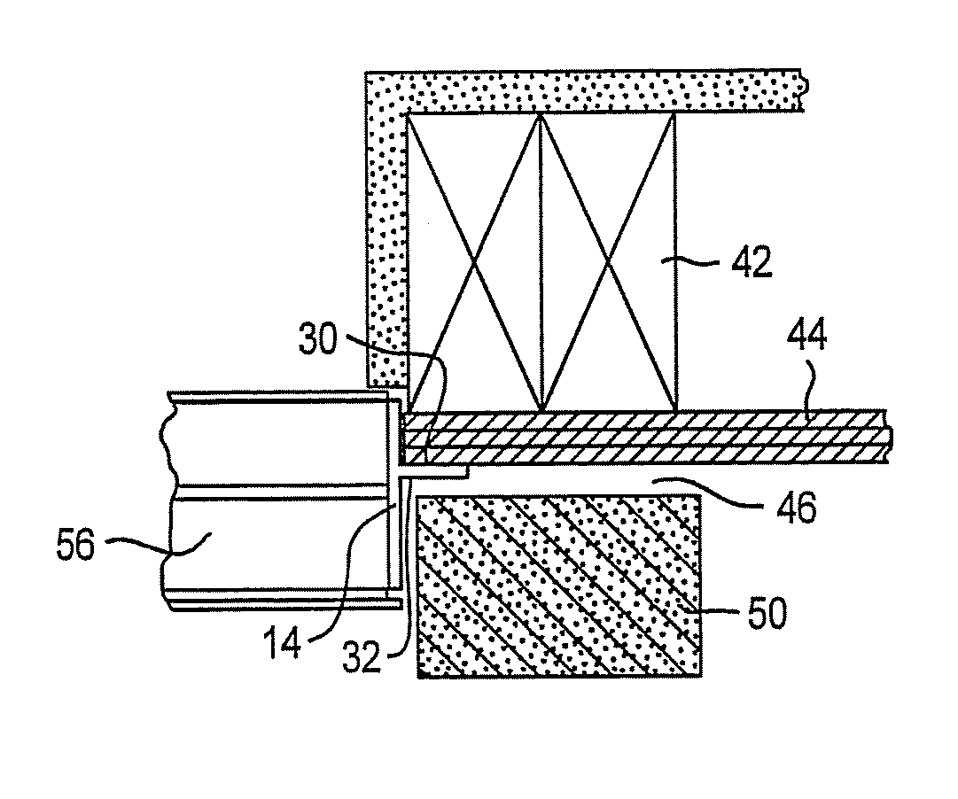

Embodiment Construction

[0032]Referring to FIG. 1 there is shown a conventional window assembly 34. This assembly 34 is comprised of an original window 52 having a frame 38 and a nail fin 48. The window 52 is disposed within an opening 36 in a wall 40. The wall 40 is comprised of studs 42, an interior material 54 such as structural framing, drywall or sheetrock, and sheathing 44. The window assembly 34 is further comprised of an exterior material 50 such as brick, masonry, or other exterior siding.

[0033]Referring to FIGS. 2-9, there is shown a replacement window and door sealing fin 14 for use in the installation of a replacement window 56 or door 57 within a rough opening 36. The rough opening 36 is located within a wall 40, the wall being comprised of studs 42, an interior material 54 and an exterior material 50. The replacement window and door sealing fin 14 may be fitted into a variety of rough opening 36 sizes by varying an amount of overlap of portions of the sealing fin 14. In FIG. 9, there is shown...


PUM


Abstract

The sealing fin is elongated, and includes a central fin portion intersecting a crosspiece portion perpendicular thereto, thus generally forming a “T” shape in a preferred embodiment and an “L” shape in another. The sealing fin may be folded into a flat position and easily rolled. In one aspect of the present invention, the sealing fin has an adhesive layer on one or more surfaces. In another aspect of the present invention, the sealing fin is rigid. In another aspect of the present invention, the sealing fin has a rectangular configuration with a hinged portion. The invention provides a method to install a sealing fin in a continuous fashion around a window or door opening.

Description

BACKGROUND OF THE INVENTION[0001]1. Field of the Invention[0002]The present invention relates generally to sealing replacement windows and doors and specifically to a replacement window and door sealing fin and method for installing same.[0003]2. Description of the Prior Art[0004]Almost every commercial and residential structure has windows and doors. Water damage around such openings is one of the most common factors leading to premature failure in building structures. An original window is generally installed in an opening using a frame with an integrated nailing fin. The fin serves two purposes, to secure the window to the structure and to help prevent the infiltration of water, air, and insects around the window's perimeter. An original door generally has a gap between the door frame and the building structure that defines the door opening. In most cases, there is little or no fin or barrier within this gap that prevents air, water and insect penetration.[0005]In the residential...

Claims


Application Information

Patent Timeline
Patent Type & Authority Patents(United States)
IPC IPC(8): E04B1/04
CPCE06B1/62E06B2001/628
Inventor MILSTEAD, ROBERT J.
Owner MILSTEAD ROBERT J
Learn More