
Method and device for imaging tomography

a tomography and imaging technology, applied in tomography, diaphragms for radiation diagnostics, instruments, etc., can solve problems such as non-uniform sampling

Inactive Publication Date: 2012-08-14
HELMHOLTZ ZENT MUENCHEN DEUT FORSCHUNGSZENTRUM FUER GESUNDHEIT & UMWELT GMBH +1
View PDF15 Cites 8 Cited by
  • Summary
  • Abstract
  • Description
  • Claims
  • Application Information

AI Technical Summary

Benefits of technology

This approach significantly reduces aliasing artifacts, improves image reconstruction accuracy, and optimizes data handling by ensuring uniform detection with conventional CT techniques, compatible with various imaging applications including medical and industrial use.

Problems solved by technology

With the conventional energy beam components having equal cross-sections, this non-uniform sampling yields in most cases either an overlap or gaps between neighboring parallel energy beam components.

Method used


Image

  • Method and device for imaging tomography
  • Method and device for imaging tomography
  • Method and device for imaging tomography

Examples


Embodiment Construction

[0052]The invention is described in the following with reference to the application in computer tomography. It is emphasized that the invention can be implemented in an analogous way with the other applications mentioned above. Furthermore, the following description of the preferred embodiments mainly refers to the step of energy beam shaping. Details of CT or other imaging devices or image reconstruction algorithms used for implementing the invention are not described as far as they are known from conventional techniques or from EP 04031043.5.

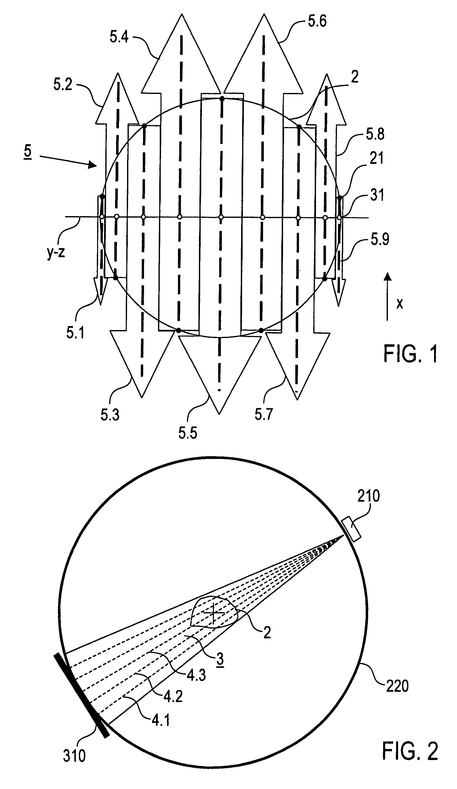
[0053]Beam shaping according to the invention is schematically illustrated in FIG. 1, which shows the 2-dimensional case of imaging a plane intersecting an object. With the circle 2 representing the ROI to be reconstructed, black dots 21 on the circle 2 are positions of an X-ray source for creating radiation beams each including one of the illustrated X-ray radiation beam components (arrows). White dots 31 represent the distribution of e.g. ni...


PUM

PropertyMeasurementUnit
distanceaaaaaaaaaa
thicknessaaaaaaaaaa
diameteraaaaaaaaaa

Abstract

An imaging method for imaging a region of investigation of an object, comprises the step of irradiating the region of investigation with at least one energy input beam along a plurality of projection directions, wherein the at least one energy input beam comprises a plurality of individual energy input beam components, wherein the energy input beam is shaped such that at least two of the energy input beam components have different cross-sections and groups of parallel energy input beam components being parallel to one of the projection directions provide a continuous irradiation of the region of investigation. Furthermore, a device for imaging the object is described.

Description

STATEMENT REGARDING FEDERALLY SPONSORED RESEARCH[0001]This invention was made with U.S. Government support under Grant DMS-020 1669 awarded by the National Science Foundation. The Government has certain rights in this invention.CROSS REFERENCE TO RELATED APPLICATIONS[0002]This is the U.S. National Stage of International Application No. PCT / EP2006 / 004781 filed May 19, 2006, which was published in English under PCT Article 21(2), which in turn claims the benefit of European Applications No. 05011135.0, filed May 23, 2005. Both applications are incorporated herein in their entirety.TECHNICAL FIELD[0003]The present invention relates to a method for imaging an object being irradiated with at least one energy input beam along a plurality of projection directions, in particular to a method for imaging an object on the basis of reconstructing an image function from Radon data comprising a plurality of projection functions measured corresponding to the plurality of projection directions. Fur...

Claims


Application Information

Patent Timeline
Patent Type & Authority Patents(United States)
IPC IPC(8): G01N23/00
CPCA61B6/032A61B6/06A61B6/482G06T11/003G06T11/005G06T2211/421A61B6/027A61B6/03G01N23/00
Inventor XU, YUANTISCHENKO, OLEGHOESCHEN, CHRISTOPH
Owner HELMHOLTZ ZENT MUENCHEN DEUT FORSCHUNGSZENTRUM FUER GESUNDHEIT & UMWELT GMBH
Learn More