Cannulation apparatus and method

Active Publication Date: 2012-08-14
WORLD HEART
View PDF59 Cites 18 Cited by
  • Summary
  • Abstract
  • Description
  • Claims
  • Application Information

AI Technical Summary

Benefits of technology

[0011]The apparatus and methods of the present invention have been developed in response to the present state of the art, and in particular, in response to the problems and needs in the art that have not yet been fully solved by currently available methods and apparatus for coring and cannulating a body part such as a heart, as well as methods and apparatus for installing a heart assist or replacement device. Thus, the present invention provides apparatus and methods for rapidly coring and cannulating a body part such as the heart with minimal risk of air emboli, thus also allowing for the installation of a heart assist or replacement device.
[0012]Some current treatments for heart disorders or diseases call for the installation of ventricular assist devices or heart replacement devices. Previous methods for installing such devices required invasive procedures to create a large opening in the chest cavity of the patient to allow installation. Current methods of installation of such devices call for cardiovascular bypass methods to be used in order to reduce the risk of air emboli during the coring of the heart and the insertion of the device.
[0013]The method and apparatus of the invention allow the remote installation of ventricular assist devices. Specifically, the method of the invention provides a rapid and / or remote or minimally invasive method for coring the left ventricular apex of the heart, removing the core, and attaching a ventricular inflow cannula to the heart. When used in surgeries in which a normal incision has been made, as well as when used remotely, the method decreases the risk of air emboli and eliminates the need for cardiovascular bypass. The method may additionally reduce the loss of blood involved in such surgeries, and may improve the comfort of the patient by minimizing the need for thoracotomy (incision into the thorax) or sternotomy (incision into the sternum) by allowing the installation of a device without direct surgical access. This may also reduce the recovery time needed after such a surgical procedure.

Problems solved by technology

This may also reduce the recovery time needed after such a surgical procedure.

Method used


Image

  • Cannulation apparatus and method
  • Cannulation apparatus and method
  • Cannulation apparatus and method

Examples


Embodiment Construction

[0049]The presently preferred embodiments of the present invention will be best understood by reference to the drawings, wherein like parts are designated by like numerals throughout. It will be readily understood that the components of the present invention, as generally described and illustrated in the figures herein, could be arranged and designed in a wide variety of different configurations. Thus, the following more detailed description of the embodiments of the apparatus, system, and method of the present invention, as represented in FIGS. 1 through 6, is not intended to limit the scope of the invention, as claimed, but is merely representative of presently preferred embodiments of the invention.

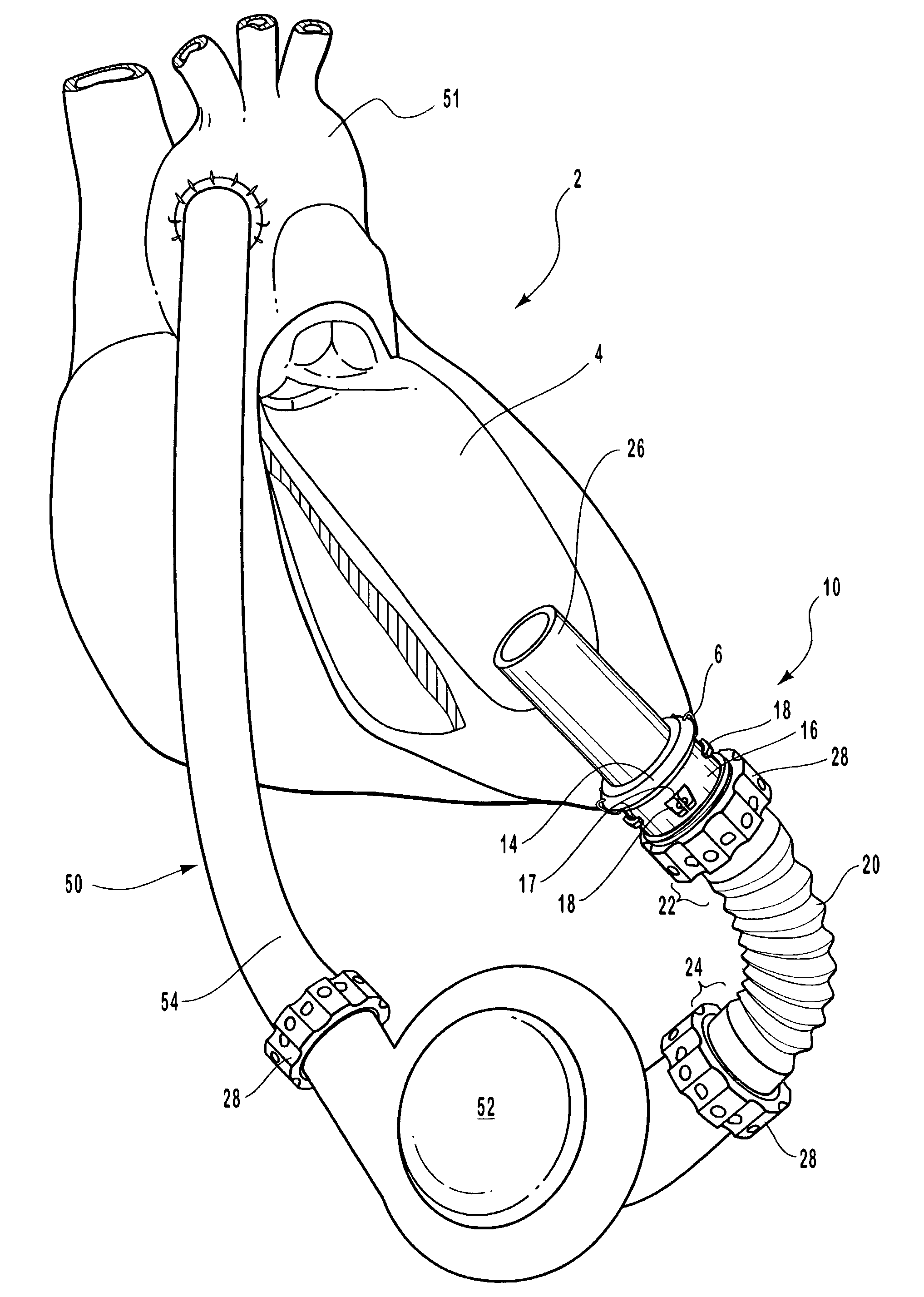
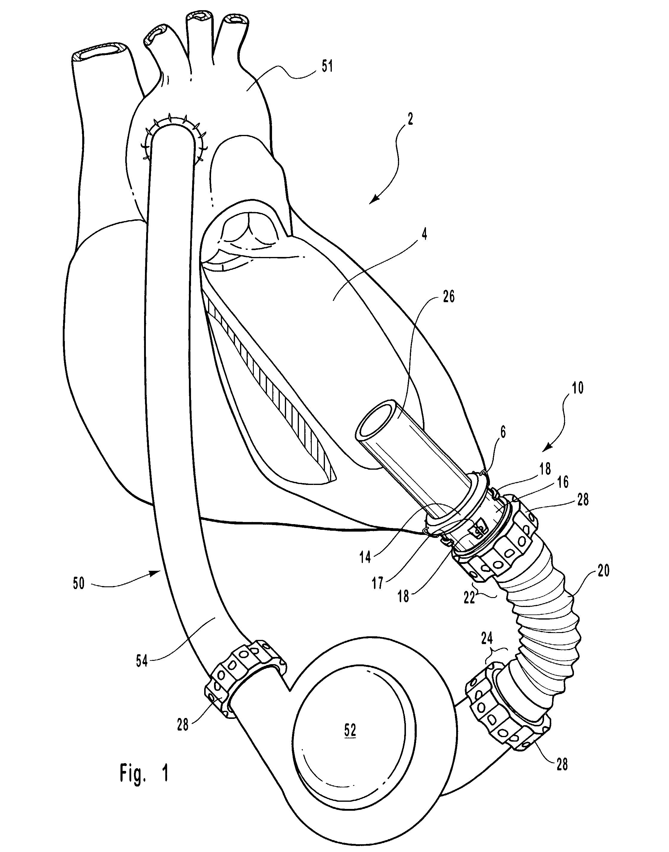
[0050]Referring now to FIG. 1, a remote cannulation assembly 10 of the invention is shown fully installed into a heart 2. The cannulation assembly 10 is shown placed into a left ventricle 4 of a heart 2 and attached to a heart assist or replacement device 52. In turn, the heart assist ...


PUM


Abstract

A remote cannulation assembly is disclosed for rapidly cannulating a body part such as a heart during a medical procedure. Cannulation is often conducted in procedures such as the installation of a ventricular assist device. The cannulation assembly of the invention utilizes an isolation valve to create a sealed fluid environment for the procedure. The invention further includes a coring assembly that may be used with the cannulation apparatus. Methods of cannulating a heart or other body part are also disclosed in which the risk of emboli is reduced. Additionally, methods of connecting and disconnecting two fluid conducting elements are disclosed.

Description

RELATED APPLICATIONS[0001]This application claims the benefit of U.S. Provisional Application Ser. No. 60 / 301,795, filed Jun. 29, 2001, entitled “Remote Cannulation Apparatus and Method.” This application is incorporated herein by reference.BACKGROUND OF THE INVENTION[0002]1. Field of the Invention[0003]The present invention relates to procedures and apparatus to assist in installing and positioning a blood pump such as a left ventricular assist device, right ventricular assist device, total artificial heart, or other devices. More specifically, the present invention relates to methods and apparatus for rapidly cannulating a heart to allow connection to such devices.[0004]2. Description of Related Art[0005]Historically, many treatments for severe forms of heart disease involved some form of open-heart surgery. Open-heart surgeries are historically costly, and generally require extended periods of convalescence. In addition, open-heart surgeries often required either large transfusio...

Claims


Application Information

Patent Timeline
IPC IPC(8): A61B17/08A61M1/10A61M1/12A61M1/36
CPCA61M1/10A61M1/3667A61M1/3666A61M1/1008A61M1/122A61M1/3659A61M1/3653A61B2017/00252A61B2017/3425A61M1/101A61M60/857A61M60/894A61M60/148A61M60/865A61M60/863A61M60/196A61M60/178
Inventor MILES, SCOTT D.BECK, KENT F.NIEMAN, TIMOTHY R.
Owner WORLD HEART
Why Eureka
Try Eureka