
Apparatus for image recognition

a technology of image recognition and apparatus, applied in scene recognition, instruments, transportation and packaging, etc., can solve the problems of difficult extraction of pedestrian motion, small pedestrian image, and inability to generate motion vectors from pedestrian images, and achieve high accuracy. the effect o

Inactive Publication Date: 2012-08-07
DENSO CORP
View PDF15 Cites 4 Cited by
  • Summary
  • Abstract
  • Description
  • Claims
  • Application Information

AI Technical Summary

Benefits of technology

The present disclosure provides an apparatus for recognizing moving objects in images with high accuracy, even when the size of the object is approximately the size of a pixel block. The apparatus uses encode information derived from discrete cosine transform and motion-compensating prediction to calculate multiple evaluation values for each pixel block. These evaluation values are then used to determine which pixel block corresponds to which object in the image. The apparatus can detect objects as small as a pixel block and can code or extract image data without substantially changing the conventional encoder / decoder.

Problems solved by technology

When the motion information is calculated for a unit of pixel blocks, the extraction of pedestrian motion is difficult due to the smallness of the pedestrian image in the screen.
That is, if the position of the pedestrian is relatively far and that makes the size of the pedestrian substantially same as or smaller than the size of the pixel block, the pedestrian image is small and motion vectors cannot be generated from the image of the pedestrian who is walking at a normal speed.
As a result, the extraction of the pedestrian motion based on those motion vectors is difficult.
On the other hand, when the motion information is calculated for every pixel, a couple of problems are encountered, such as a signal-noise distinction problem due to the pseudo-motion of stationary objects caused by the camera movement and / or uneven brightness, or a calculation load problem that the detection of the pedestrian requires an huge amount of calculation.
Further, maintaining consistency throughout the pixel-by-pixel processing of the detection method and the pixel block processing of the widely-used MPEG format may sometimes be difficult.

Method used


Image

  • Apparatus for image recognition
  • Apparatus for image recognition
  • Apparatus for image recognition

Examples


Embodiment Construction

[0028]An embodiment of the present disclosure is explained in the following with reference to the drawings.

[0029](System Structure)

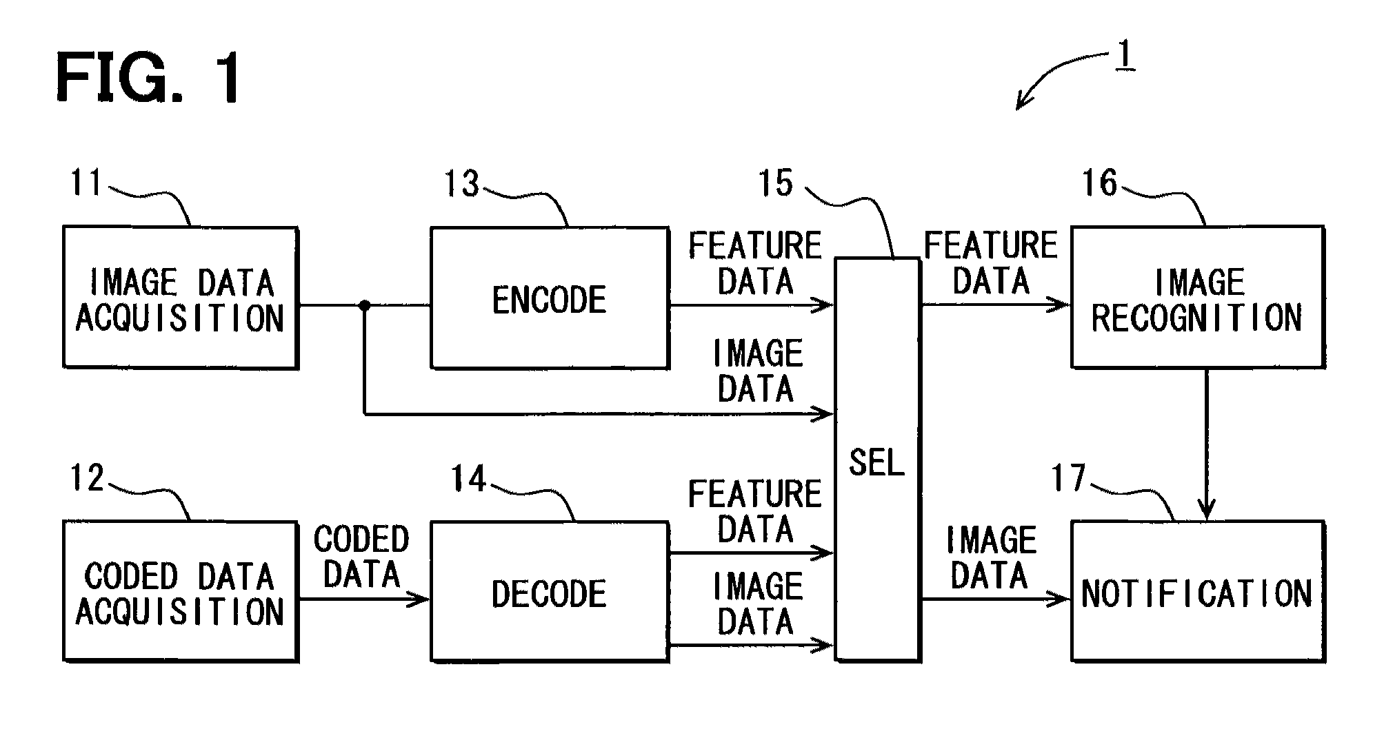
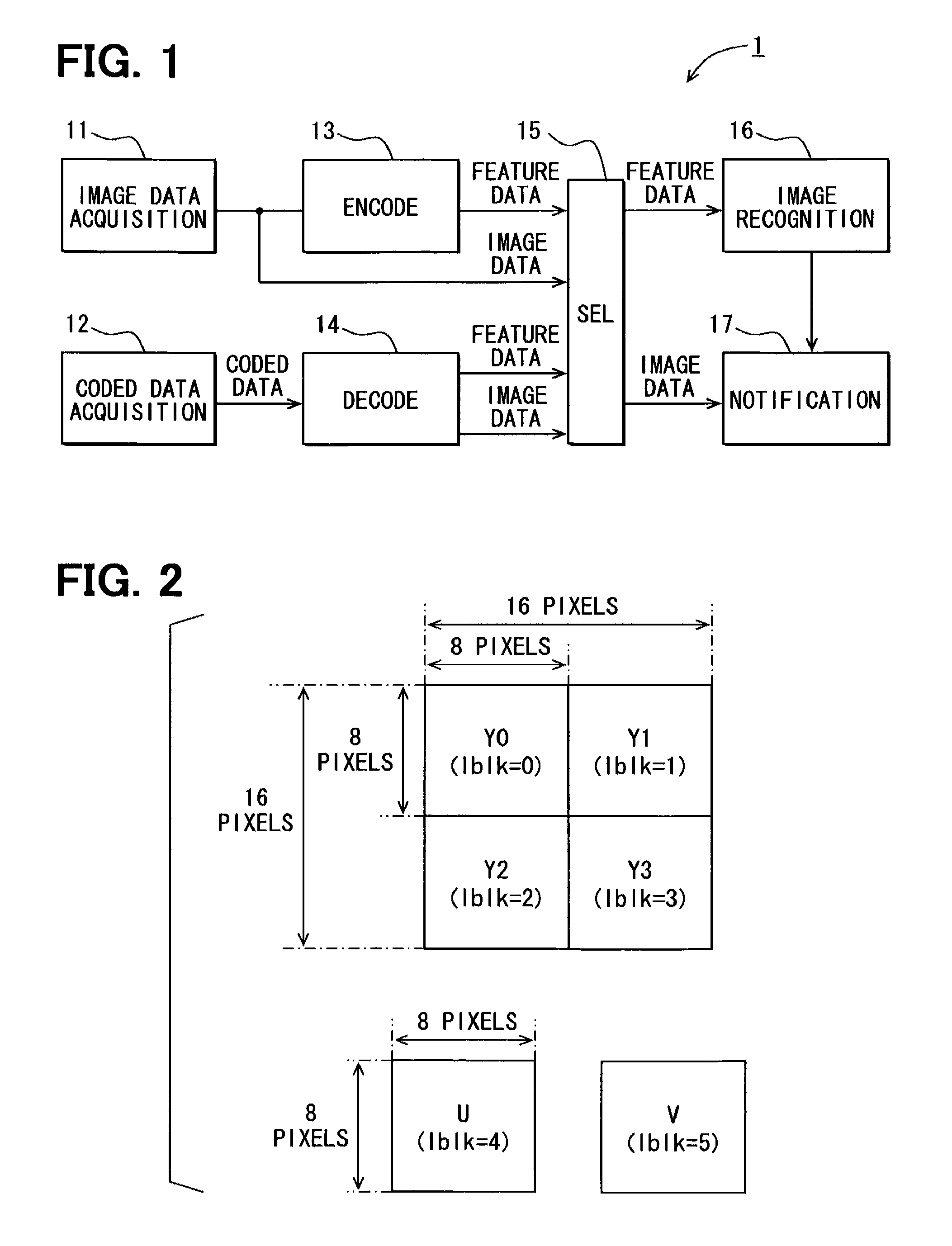
[0030]FIG. 1 is about an electronic apparatus 1 for use in a vehicle that recognizes various objects including a pedestrian, in particular, based on acquired image information. The recognized object is then notified for the driver of the vehicle. The block diagram in FIG. 1 shows an overall structure of the electronic apparatus 1.

[0031]As shown in FIG. 1, the electronic apparatus 1 includes an image data acquisition unit 11 which acquires image data of a moving image derived from a camera in the vehicle, a coded data acquisition unit 12 which acquires coded data of moving image encoded in MPEG format (i.e., an MPEG-1 format in the present embodiment) from a stationary camera that images roads and other objects through wireless communication with a roadside device or the like, an encode unit 13 for coding the data from the acquisition unit 11 in MPEG form...


PUM


Abstract

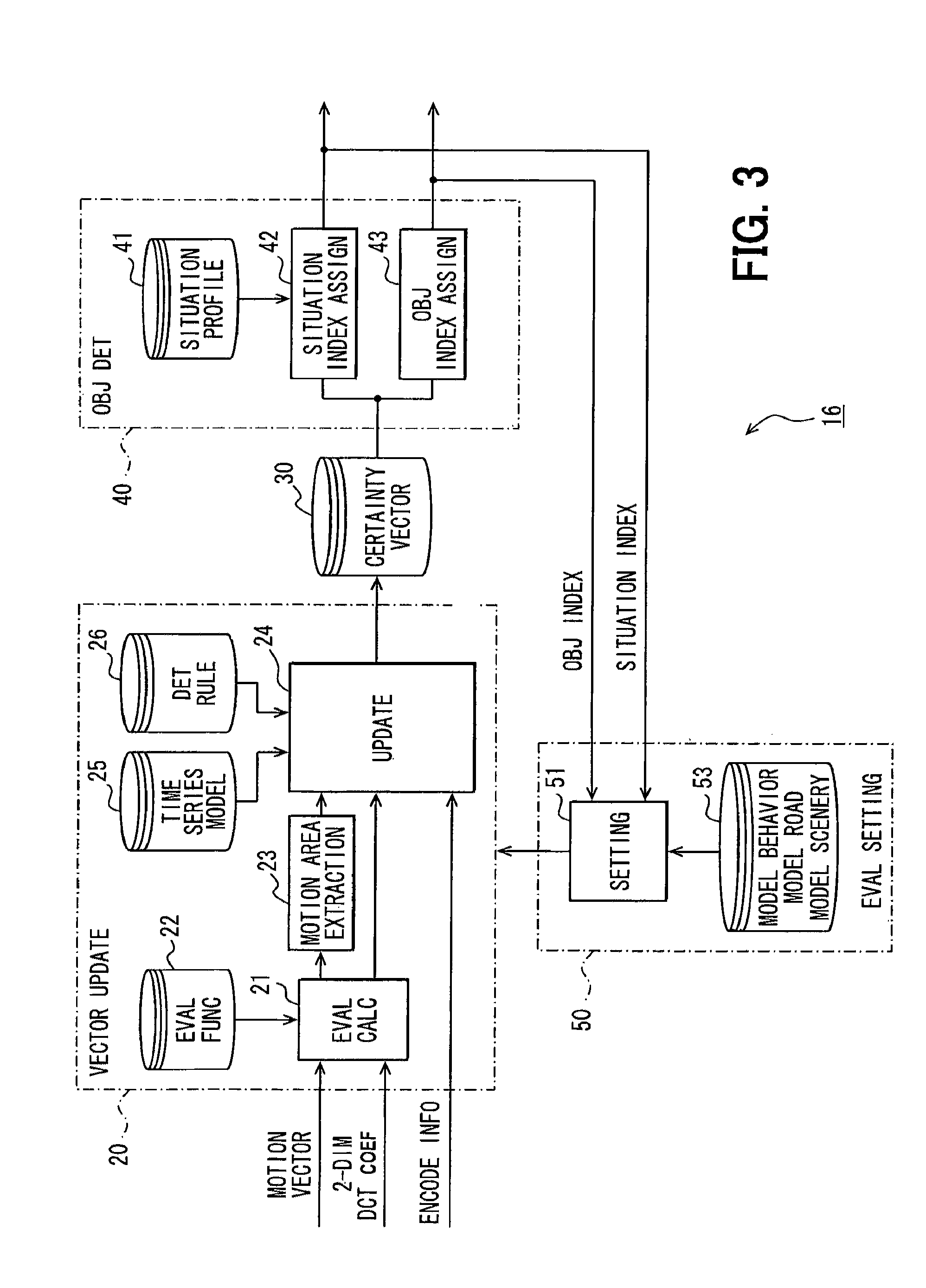
An image recognition apparatus includes an image recognition unit, an evaluation value calculation unit, and a motion extraction unit. The image recognition unit uses motion vectors that are generated in the course of coding image data into MPEG format data or in the course of decoding the MPEG coded data by the evaluation value calculation unit and the motion extraction unit as well as two dimensional DCT coefficients and encode information such as picture types and block types for generating the evaluation values that represent feature of the image. The apparatus further includes an update unit for recognizing the object in the image based on the determination rules for a unit of macro block. The apparatus can thus accurately detect the motion of the object based on the evaluation values derived from DCT coefficients even when generation of the motion vectors is difficult.

Description

CROSS REFERENCE TO RELATED APPLICATION[0001]The present application is based on and claims the benefit of priority of Japanese Patent Application No. 2008-122258 filed on May 8, 2008, the disclosure of which is incorporated herein by reference.FIELD OF THE INVENTION[0002]The present disclosure generally relates to an image recognition apparatus that recognizes an object by using encode information generated in the course of encoding or decoding of an image performed by employing the motion-compensating prediction and the discrete cosine transform.BACKGROUND INFORMATION[0003]Conventionally, information on the motion of the object is regarded as important when the object is extracted from a motion picture that is captured by a camera in the vehicle or the like.[0004]More practically, a method that calculates motion vectors for a unit of pixel blocks (e.g., a pixel block having 16×16 pixels), or a method that highly accurately detects the motion for every pixel has been used for image ...

Claims


Application Information

Patent Timeline
Patent Type & Authority Patents(United States)
IPC IPC(8): G06K9/00G06K9/36B60R1/00G06T7/20G08G1/16H04N19/102H04N19/134H04N19/136H04N19/139H04N19/14H04N19/189H04N19/196H04N19/423H04N19/50H04N19/503H04N19/51H04N19/513H04N19/577H04N19/60H04N19/61H04N19/625H04N19/80H04N19/91
CPCG06K9/00369G06K9/00805H04N19/51G06V40/103G06V20/58
Inventor SASAKI, MIKIO
Owner DENSO CORP
Learn More