Blower for vehicles

a technology for blowers and vehicles, applied in the direction of positive displacement liquid engines, piston pumps, liquid fuel engines, etc., can solve the problems of uneven air flow distribution in the upper and lower parts of the blower, and achieve the effects of preventing deformation of the outer case, reducing suction noise, and preventing a drooping of the air filter

Active Publication Date: 2012-08-07
HANON SYST
View PDF7 Cites 7 Cited by
  • Summary
  • Abstract
  • Description
  • Claims
  • Application Information

AI Technical Summary

Benefits of technology

[0022]Accordingly, the present invention has been made to solve the above-mentioned problems occurring in the prior arts, and it is an object of the present invention to provide a blower for vehicles, which includes guide walls formed on a bypass passageway formed between a scroll case and an outer case to send the indoor air and the outdoor air to a lower suction opening of the scroll case, thereby reducing suction noise by guiding a uniform flow of air introduced into the lower suction opening, preventing deformation of the outer case, and preventing a droop of the air filter by supporting a lower portion of an air filter when an intake duct injection-molded in a vertically parted mold is applied thereto.

Problems solved by technology

However, the blower 10, to which the unidirectional suction type blower fan 31 is applied, has a problem in that an air flow distribution is not uniform in the upper and lower parts of the blower 10 since the air is mainly discharged along an inclined surface of the hub plate 31 as shown in FIG. 2 when the air is discharged from the blower fan 31 in the radial direction.

Method used


Image

  • Blower for vehicles
  • Blower for vehicles
  • Blower for vehicles

Examples


Embodiment Construction

[0036]Reference will be now made in detail to the preferred embodiment of the present invention with reference to the attached drawings.

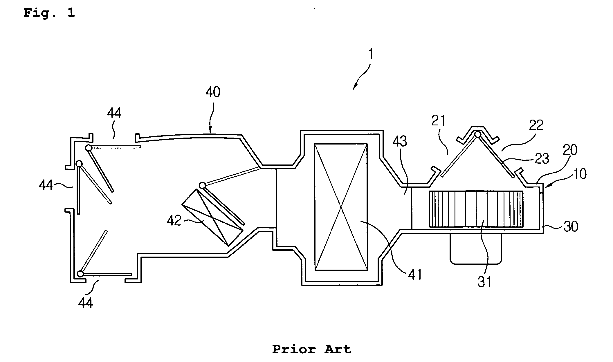
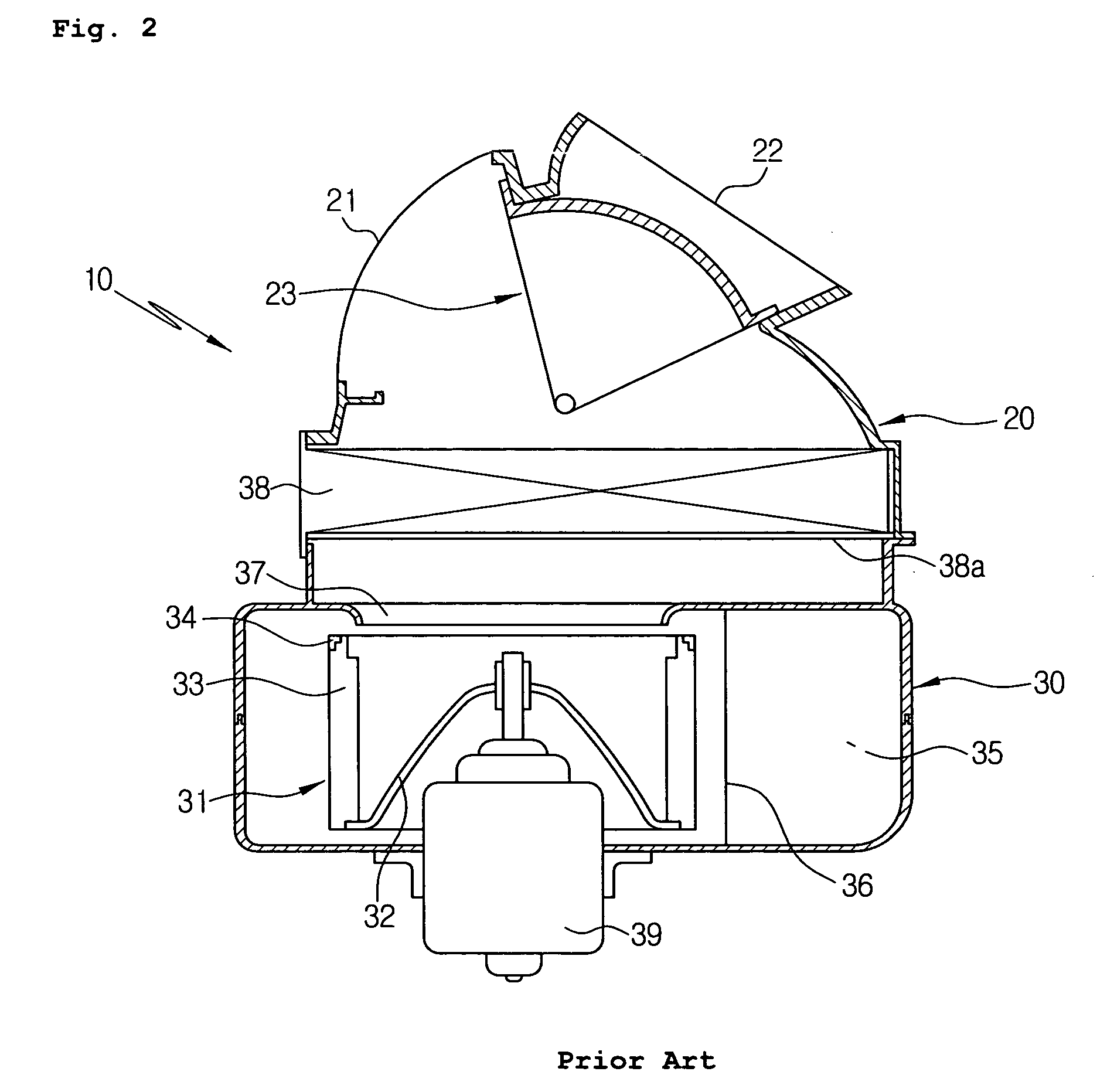
[0037]In the present invention, description of the same configuration and action as the prior arts will be omitted.

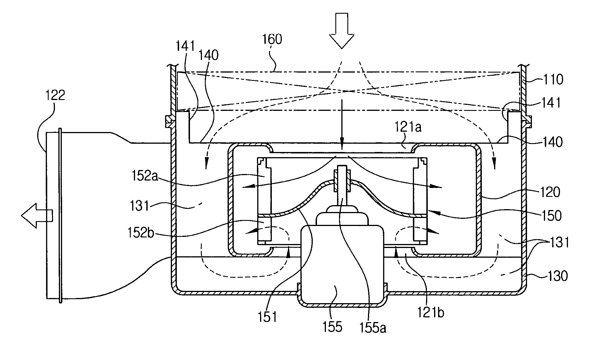
[0038]FIG. 5 is an exploded perspective view of a blower for vehicles according to a preferred embodiment of the present invention, FIG. 6 is a plan view showing a state where an intake duct is omitted from the blower for vehicles according to the present invention, FIG. 7 is a cross-sectional view taken along the line of A-A of FIG. 5, FIG. 8 is a cross-sectional view taken along the line of B-B of FIG. 5, and FIG. 9 is a view showing various examples of a guide wall of the blower according to the present invention.

[0039]As shown in the drawings, the blower 100 according to the present invention includes a scroll case 120, a bidirectional suction type blower fan 150, an outer case 130, and an intake duct 110.

[0040]The bidirectional suc...


PUM


Abstract

The present invention relates to a blower for vehicles, which includes guide walls formed on a bypass passageway formed between a scroll case and an outer case to send the indoor air and the outdoor air to a lower suction opening of the scroll case, thereby reducing suction noise by guiding a uniform flow of air introduced into the lower suction opening, preventing deformation of the outer case, and preventing a droop of the air filter by supporting a lower portion of an air filter when an intake duct injection-molded in a vertically parted mold is applied thereto.

Description

[0001]This application claims priority from Korean Patent Application No. 10-2007-0036142 filed Apr. 12, 2007 and Korean Patent Application No. 10-2008-0024214 filed Mar. 17, 2008, 2008, each of which are incorporated herein by reference in their entireties.BACKGROUND OF THE INVENTION[0002]1. Field of the Invention[0003]The present invention relates to a blower for vehicles, and more particularly, to a blower for vehicles, which includes guide walls formed on a bypass passageway formed between a scroll case and an outer case to send the indoor air and the outdoor air to a lower suction opening of the scroll case, thereby reducing suction noise by guiding an uniform flow of air introduced into the lower suction opening, preventing deformation of the outer case, and preventing a droop of the air filter by supporting a lower portion of an air filter when an intake duct injection-molded in a vertically parted mold is applied thereto.[0004]2. Background Art[0005]In general, an air condit...

Claims


Application Information

Patent Timeline
Patent Type & Authority Patents(United States)
IPC IPC(8): B60H1/00
CPCB60H1/00471B60H1/00514F04D29/4226F04D29/703B60H2001/00092
Inventor KANG, BOKSUNKIM, YONGSANGLEE, YONGHUNGPARK, YUNCHEOL
Owner HANON SYST
Why Eureka
Try Eureka