
Pump unit comprising a main pump and a charge pump with a variable pump capacity

Active Publication Date: 2012-07-31
ROBERT BOSCH GMBH
View PDF11 Cites 7 Cited by
  • Summary
  • Abstract
  • Description
  • Claims
  • Application Information

AI Technical Summary

Benefits of technology

[0008]The pump unit according to the present invention comprises a main pump and a charge pump having a variable pump capacity. An adjusting means is provided for adjusting the pump capacity of the charge pump; the adjusting means is acted upon with an adjusting force that is dependent on an inlet pressure of the main pump. By generating an adjusting force that is dependent on the pressure present at the inlet side of the main pump, it is ensured that there is an immediate reaction to the adjustment of the pump capacity of the charge pump if the inlet pressure of the main pump changes. In this manner it is possible to prevent pressure spikes, and it is ensured that an undersupply of the main pump and, therefore, an occurrence of cavitation are reliably prevented. This has a positive effect on the service life of the main pump. The decisive factor is that the pump capacity is adjusted as a function of the pressure on the inlet side. Pressure fluctuations that are due, e.g., to a filter located between the main pump and the charge pump, have no effect.
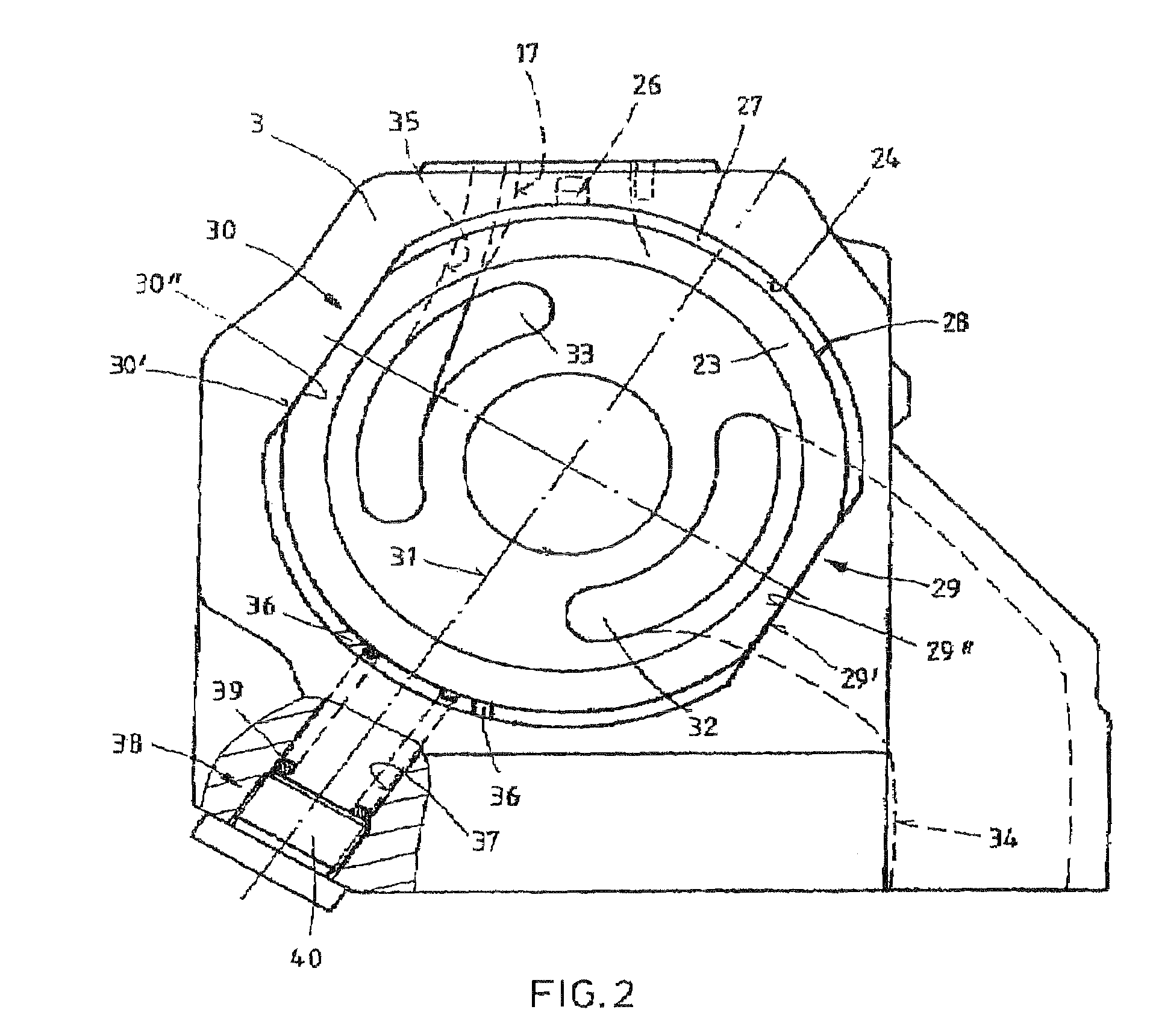
[0016]In particular, it is preferred that the stroke ring is acted upon with a restoring force, and the direction of the restoring force is perpendicular to a hydraulic force generated by a delivery-side inner pressure on the stroke ring. It is particularly preferred for the hydraulic force generated by the pressure on the inner side of the stroke ring to be simultaneously perpendicular to a mating surface formed by the flat section. The force generated in the interior of the stroke ring via the delivery pressure may therefore be reliably supported by the flat section. The force generated by the delivery pressure on the stroke ring therefore does not affect the control. An improvement of the control behavior is attained, since it is only dependent on the restoring force and the inlet pressure of the main pump.

Problems solved by technology

In the known hydraulic systems that include two serially connected hydraulic pumps, it is disadvantageous that the pump capacity of the first pump, which supplies the second pump with pressure medium, is not regulated as a function of the pressure that acts on the inlet side of the second pump.

Method used


Image

  • Pump unit comprising a main pump and a charge pump with a variable pump capacity
  • Pump unit comprising a main pump and a charge pump with a variable pump capacity
  • Pump unit comprising a main pump and a charge pump with a variable pump capacity

Examples


Embodiment Construction

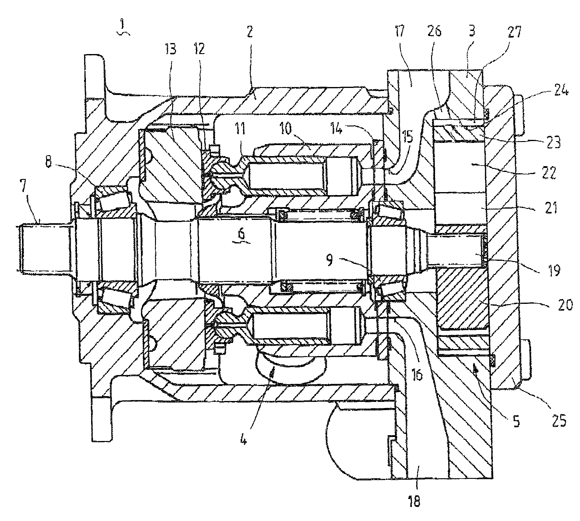
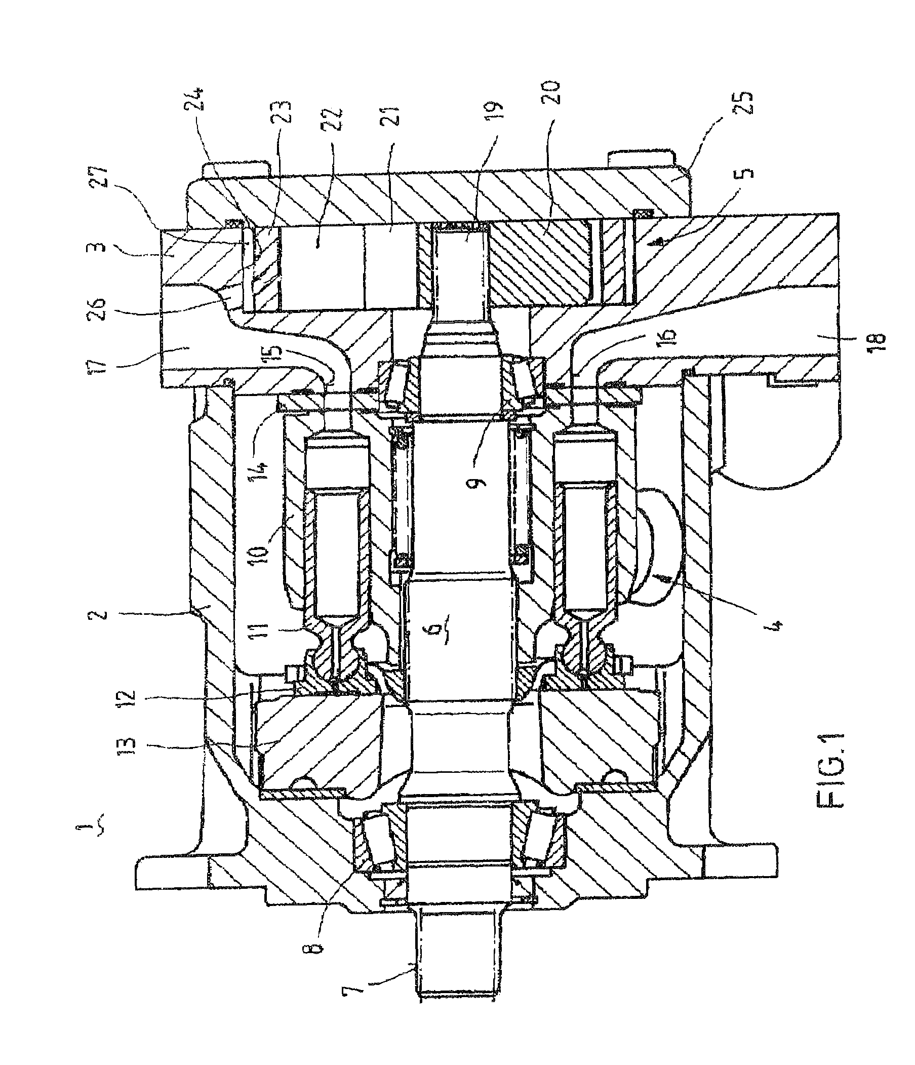
[0020]FIG. 1 shows a preferred embodiment of a pump unit 1, according to the present invention, which includes a housing having a pot-shaped housing part 2 and a further housing part that closes pot-shaped housing part 2. The further housing part is designed as terminal plate 3. A main pump 4 is located in the interior of pot-shaped housing part 2. A charge pump 5 is located in a side of terminal plate 3 that faces away from pot-shaped housing part 2.

[0021]Main pump 4, which is designed as an axial piston machine in the embodiment shown, and charge pump 5 are driven by a common drive shaft 6. Drive shaft 6 includes a shaft end which extends out of pot-shaped housing part 2 in the region of the base. Toothing 7 is formed on the shaft end of drive shaft 6. Toothing 7 is used to non-rotatably connect drive shaft 6 to a device which generates torque.

[0022]Common drive shaft 6 is rotatably supported in the housing of pump unit 1 using a first bearing 8 and a second bearing 9, and is ther...


PUM


Abstract

A pump unit includes a main pump (4) and a charge pump (5), the pump capacity of which is adjustable via an adjusting element. To adjust the pump capacity of the charge pump (5), an adjusting element of the charge pump (5) is acted upon by an adjusting force which is dependent on the inlet pressure of the main pump (4).

Description

CROSS-REFERENCE[0001]The invention described and claimed hereinbelow is also described in PCT / EP2008 / 054864, filed on Apr. 22, 2008 and DE 10 2007 022 949.8, filed May 16, 2007 and DE 10 2007 032 103.3, filed Jul. 10, 2007. These German Patent Applications, whose subject matter is incorporated here by reference, provides the basis for a claim of priority of invention under 35 U.S.C. 119 (a)-(d).BACKGROUND OF THE INVENTION[0002]The present invention relates to a pump unit comprising a main pump and a charge pump having a variable pump capacity.[0003]Publication DE 100 45 118 A1 makes known a hydraulic system comprising a main pump and a precompression pump. The hydraulic system presented therein includes two pumps in a serial arrangement, it being possible to adjust the pump capacity of each of the two pumps. The precompression pump, the delivery side of which is connected to an inlet line of the main pump, may be adjusted using an adjusting device. An open-loop or closed-loop contro...

Claims


Application Information

Patent Timeline
IPC IPC(8): F04B23/10F04B49/12F04C14/02
CPCF04B23/106F04B49/12F04C14/02F04B2205/01F04B2205/06F04B1/07F04B23/12
Inventor MERZ, STEFANMOHN, ULRICH GORDONSCHEERER, RENE CONSTANTINZUG, MARTIN JOSEF
Owner ROBERT BOSCH GMBH
Learn More